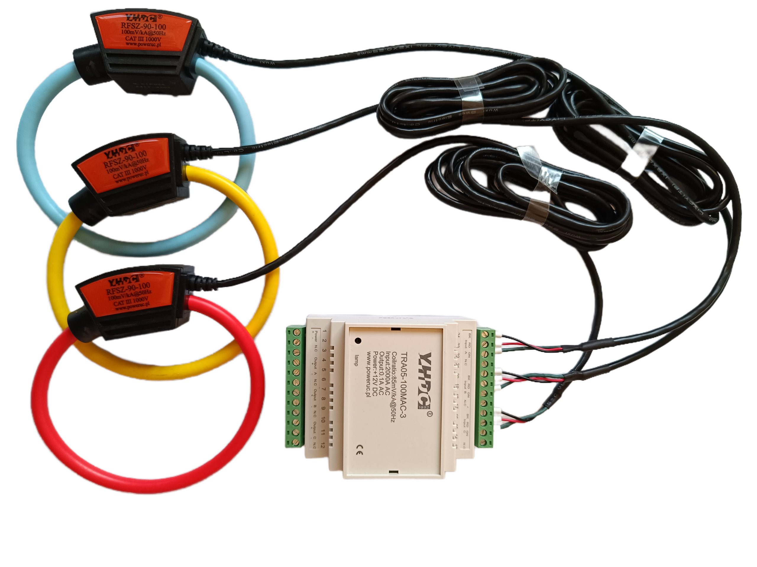
Rogowski coils, also known as hollow coils or flexible current transformers, have gained widespread application in power monitoring, high-frequency pulse current measurement, and high-current protection due to their significant advantages such as non-magnetic saturation, wide measurement range, and easy installation. However, in practical applications, Rogowski coils cannot typically be directly connected to measuring instruments but must be used in conjunction with an integrator.
1. The Physical Nature of the Rogowski Coil: di/dt Sensor
The operating principle of the Rogowski coil is based on Faraday’s law of electromagnetic induction. When the measured current i(t) passes through the center of the coil, an induced electromotive force e(t) is generated within the coil. Its mathematical expression is:
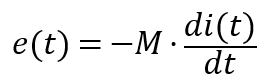
Here, M represents the mutual inductance coefficient between the coil and the primary conductor.
From the formula, it can be seen that the output voltage of the Rogowski coil does not directly correspond to the magnitude of the current, but is proportional to the rate of change (derivative) of the current. This means:
• If the current is a constant direct current, the output of the Rogowski coil is zero.
• If the current is a sine wave, the output voltage will lead the current by 90° in phase, and its amplitude will increase linearly with frequency.
Therefore, to reconstruct the true current waveform i(t), the output signal from the coil must undergo mathematical integration processing.
2. Core Functionality of the Integrator
The integrator plays a crucial role in the Rogowski coil measurement system, with its functions primarily manifested in the following three aspects:
1 Waveform Reconstruction (Integration): An electronic integration circuit (typically an active integrator composed of operational amplifiers) converts the di/dt signal into a voltage signal proportional to i(t).
2 Phase Correction: Compensates for the 90° phase lead generated by the Rogowski coil, ensuring the output signal is in phase with the original current signal. This is critical for power measurements, such as calculating power factor.
3 Signal Conditioning and Amplification: The raw induced voltage from the current loop is typically very weak (millivolt level). The integrator amplifies it to standard levels and enhances drive capability for long-distance transmission or load driving.
3. Comparative Analysis of Common Output Types for Integrators
Depending on the specific requirements of the backend receiving equipment (such as electricity meters, PLCs, oscilloscopes, or relay protection devices), integrators are designed with multiple output formats. The following table provides a detailed comparison of these common output types:
| Output Type | Typical Specifications | Signal Characteristics | Primary Applications | Advantages | Disadvantages |
| Instantaneous voltage output | 333mV AC, 1V AC | AC Waveform | Digital Energy Meters, Power Analyzers | High safety (no secondary open-circuit high voltage), excellent linearity | Limited transmission distance, susceptible to electromagnetic interference |
| Instantaneous current output | 1A AC, 5A AC | AC Waveform | Replacing traditional current transformers (CTs), relay protection | Compatible with legacy equipment, strong drive capability, suitable for remote transmission | High power consumption, requiring high-power power supply support |
| Standard analog signal | 4-20mA DC, 0-1V DC | DC/Process Signal | PLCs, DCS, industrial automation control systems | Strong anti-interference capability (4-20mA), easy system integration | Loss of original waveform information, reflecting only the effective value |
| Output without integrator | Voltage(di/dt) | AC Differential Waveform | High-frequency transient analysis, data acquisition devices with built-in integration capabilities | Extremely high bandwidth, no integral drift, fastest response | Cannot directly read current values, requiring complex backend processing |
This is currently the most prevalent output method for Rogowski coils. 333mV represents the standard low-voltage transformer specification widely adopted in North America and internationally. The primary advantage of this output method is safety: even if the secondary circuit is disconnected, it does not generate lethal high voltages like traditional current transformers. It perfectly preserves current harmonic information, making it ideal for high-precision power quality analysis.
To maintain compatibility with secondary instruments originally designed for traditional core-type CTs, integrators can output 1A or 5A currents. This type of integrator essentially functions as a “voltage-to-current” power amplifier. It resolves the issue of Rogowski coils being unable to directly drive high-impedance loads. However, due to the need to output larger currents, the integrator’s own power consumption and physical size increase significantly.
In industrial automation, users often require only the RMS value of current without needing to inspect waveforms. These integrators incorporate internal RMS-DC conversion circuits that transform complex AC signals into stable DC signals. The 4-20mA current loop output offers exceptional noise immunity, making it ideal for long-distance transmission to PLC or DCS systems.
In specialized scientific applications, such as lightning current measurement or high-energy physics experiments, users may directly capture the raw di/dt signal from the Rogowski coil. This approach bypasses bandwidth limitations and low-frequency drift inherent to integrators, enabling digital integration via post-processing algorithms to achieve extremely high measurement bandwidths (up to several MHz or higher).
4. Summary
The integrator addresses core issues of waveform reconstruction, phase correction, and signal amplification.
Selecting the appropriate output type depends on your backend equipment:
•For precision and safety, choose 333mV/1V AC;
•For compatibility with legacy systems, choose 1A/5A AC;
• For industrial monitoring, choose 4-20mA DC;
•When using metering equipment compatible with Rogowski coils or conducting high-frequency research, consider utilizing the direct di/dt output.
By properly matching the Rogowski coil with the integrator, you can fully leverage its non-saturating, wide-range capabilities to achieve precise control over complex current environments.