
Product family
AC current transformers from 0.1 A board-level sensing to 5000 A busbar monitoring
Split-core CTs for live retrofits, class 0.2S–1 panel CTs with 1 A/5 A secondaries, PCB-mount nanocrystalline and permalloy CTs, ferrite CTs for 2–500 kHz switching currents, and three-phase assemblies. Choose the construction below, then narrow the table by input, output and mounting.
Each type solves a different installation problem. Pick the one that matches how the CT will be fitted, then compare models in its table.
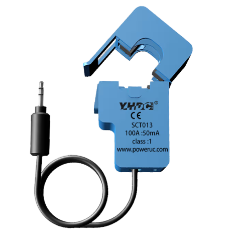
 Split-core CTs 72 models The conductor is already energised or cannot be disconnected: retrofit sub-metering, building energy monitoring, temporary or IoT measurement points. 1 A – 5000 A rated input Φ6 mm round to 220×80 mm windows mA, 1 A/5 A, 0.333 V, 1–10 V or rectified DC output
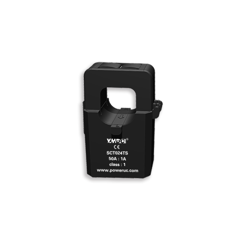
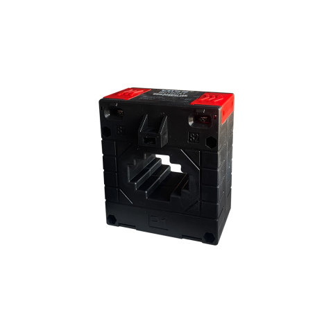 Low-voltage distribution CTs (1 A / 5 A) 14 models New switchboards or meter panels up to 0.72 kV that need a 0.1, 1 or 5 A secondary at class 0.2S–1 for meters or relays. 50 A – 4000 A rated input Class 0.2S, 0.2, 0.5S, 0.5 or 1 Plate or busbar fixing; DIN-rail on 6 BCT models
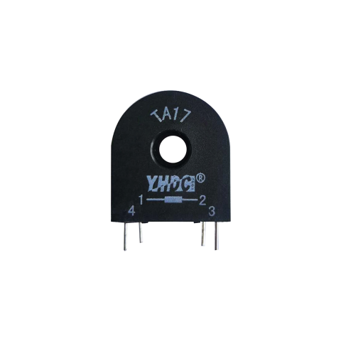 Precision PCB and panel CTs 51 models You are designing the meter, charger, inverter or analyser: a solid-core CT feeding mA into your own burden resistor and ADC. 5 A – 800 A in, 2 mA – 0.4 A out Nanocrystalline, permalloy or silicon-steel core 32 models rated 20 Hz – 20 kHz
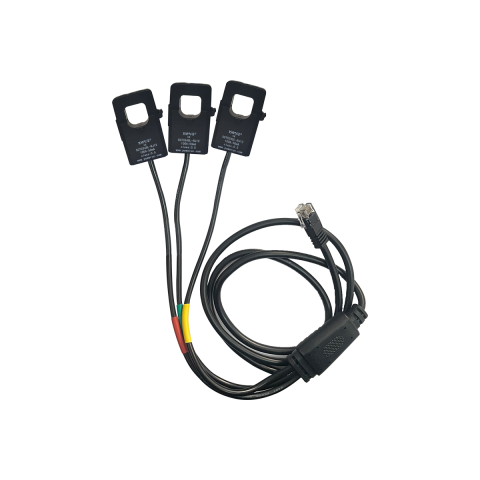 Three-phase CT assemblies 15 models All three phases must be measured with one part: three-window solid-core blocks for new builds, or split-core sets on one RJ12 plug. 5 A – 1000 A rated input Solid-core blocks, 3×Φ6.5 to 3×Φ40 mm Split-core sets with RJ12, 0.2% – 1%
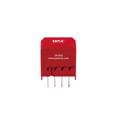 Built-in primary PCB CTs 16 models The current is small (up to 25 A) and runs on the PCB: the primary winding is integral, so no conductor passes through a window. 0.1 A – 25 A rated input 1.25 mA – 0.1 A output, PCB pins 2 – 3.5 kV dielectric strength
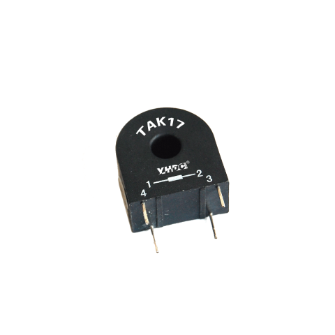 High-frequency ferrite CTs 13 models The current is at switching frequency, not 50/60 Hz: welding inverters, arc and plasma supplies, IGBT stage monitoring. 2 kHz – 500 kHz 5 A – 600 A rated input Mostly PCB-mount, Φ5 – Φ35 mm windows
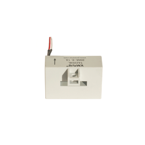 Busbar-mount power-unit CTs 10 models The CT has to sit directly on a copper busbar inside power equipment, with high isolation and a flying-lead output. 15 A – 800 A rated input Busbar slots from 4×17 mm to 9×62 mm 6 kV dielectric on most models
Also in this family: DC-immune CTs (3) · composite core tolerates a DC component SMD CTs (2) · surface-mount nanocrystalline Multi-range CT (1) · selectable 10/30/50/70 A AC current switch (1) · self-powered, switches at 2 A AC
Already know a key value? Each link opens the product table with that filter applied, and the number shows how many models match.
Can the conductor be opened? If not, only split-core will fit.
The primary current range removes most models in one step.
Match the meter or ADC input. Most models give a mA output; these find the rest.
Board, panel, cable or DIN-rail mounting usually fixes the family.
All four measure current without contact. Signal type, current range and installation decide which fits. Figures are the extremes of each PowerUC product family, not of one model.
| This family Solid-core CT | This family Split-core CT | Rogowski coil + integrator | Hall-effect sensor | |
|---|---|---|---|---|
| Measures | AC only | AC only (DC-output models rectify an AC input) | AC only | AC and DC |
| Range in our catalogue | 0.1 A – 4000 A | 1 A – 5000 A | Coils 30 A – 500 kA; integrators 100 A – 10 kA | 0.25 A – 5000 A |
| Stated accuracy | Class 0.2S – 1 on 1 A/5 A types; precision types state linearity better than 0.2% or 0.1% | 0.2S – 5% by model | 0.5% – 1% (one integrator 2%) | 0.5–1% closed-loop; 1% open-loop and split-core |
| Installation | Conductor threaded through the window, or PCB/busbar mount; the circuit must be opened | Clamps around a live conductor | Flexible coil wraps a cable or busbar; integrator on DIN rail or plate | Through-hole or split-core housing |
| Power and saturation | Passive; the magnetic core can saturate on overcurrent or a DC offset | Passive; the magnetic core can saturate on overcurrent or a DC offset | Air core does not saturate; output is di/dt, so an integrator is required | Active: needs a 3.3–5 V or ±12–24 V supply |
| Output | mA, 0.1/1/5 A, 2.2 V or 3.53 V | mA, 1 A/5 A, 0.333 V, 1–10 V AC or DC | Coil mV/kA; integrator 0.333–10 V, 4–20 mA or 20 mA–5 A | 2.5 V ±0.625 V or ±2 V, ±4 V, or mA (closed-loop) |
Ranges come from the rated input, accuracy and output data of the PowerUC current transformer, Rogowski coil and Hall sensor ranges. Rogowski coils vs current transformers, in detail
Application notes that show which CT types and models each system design uses.
Solid-core CTs for new cabinets, split-core CTs for retrofits, and Rogowski coils for main feeders and busbars.
Operating current is sampled with a nanocrystalline PCB CT such as TA17, alongside a ZDA13A for Type B leakage protection.
One CT per phase on the inverter AC output feeds power, phase-loss and imbalance calculation; DC string current needs Hall sensors.
Many frames in this range already exist in several electrical and mechanical variants. Start from the closest listed model and tell us what has to change.
Distribution CTs are listed with 0.1 A, 1 A and 5 A secondaries, and other secondary currents can be specified.
SCT024TS is listed with 20 mA–5 A, 0.333 V and 1/3/5 V outputs; -D versions add a rectified DC output.
TA8348/8349/8350 come with nanocrystalline, permalloy, silicon-steel or DC-immune composite cores.
Leads, screw terminals, RJ11/RJ12 or a 3.5 mm plug; SCT013 offers RJ12 on request and SCT025B terminals or leads.
BCT and BH distribution CTs are listed in classes 0.2S, 0.2, 0.5S, 0.5 and 1.
Seven split-core sizes, Φ6 to Φ52 mm, also come as three-phase sets on one RJ12 connector.
Short answers to the questions that most often decide a CT selection.
Send the operating conditions, not only a part number. The closest model from the table plus these values lets us confirm a standard part or a variant.
Include in your request


Copyright © 2026 PowerUC Electronics Co.