
The reason for the prevalence of the 2.5V ±0.625V and 2.5V ±2V output ranges for Hall-effect open-loop current sensors
is based on their principle of operation, supply voltage, and optimized design for interfacing with subsequent analog-to-digital converters (ADCs).
The technical reasons behind these standard output ranges are explained in detail below.
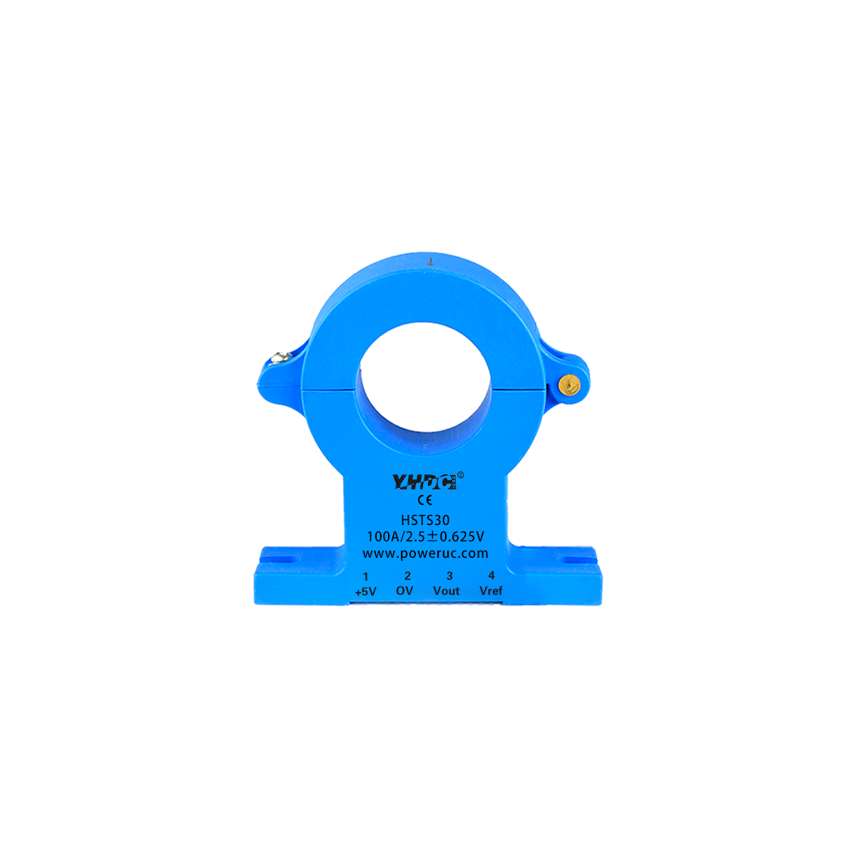
2.5V is the standard output voltage for Hall effect current sensors in a zero current (or static) state, often referred to as
Quiescent Output Voltage.
Unipolar Power Supply: Most modern Hall effect current sensors are designed to be powered by a unipolar 5V supply.
Center Point Setting: To measure bi-directional currents (forward and reverse), the sensor’s zero-current output must be set at half the supply voltage VCC, i.e., 5V / 2 = 2.5V.
Mechanism of Operation: The output voltage rises from 2.5V when current flows in the forward direction and falls from 2.5V when current flows in the reverse direction.
This design ensures that the entire output range can represent positive and negative currents in a single-supply system without the need for a negative voltage.
2.5V ±0.625V corresponds to an output span of 1.875V to 3.125V (total 1.25V).
The selection of this range is closely related to the optimized interface of the ADC and the system accuracy.
ADC Interface: Many microcontrollers (MCUs) and DSPs use 3.3V for I/O voltages and ADC reference voltage (VREF).
Optimizing the ADC Dynamic Range: Sensor designers avoid using the full 0V–5V range to prevent saturation.
The signal is limited to within 3.3V for optimal resolution on a 3.3V ADC.
Advantage of 1.25V Span: A ±0.625V range offers safety margins, prevents clipping, and maintains high linearity in 3.3V systems.
ADC Resolution: This span can be matched to ADC resolutions (e.g., 10-bit or 12-bit) to minimize quantization error at rated current.
2.5V ±2V corresponds to 0.5V–4.5V (total span 4V). This range maximizes signal dynamic range and improves noise immunity.
Close to Rail-to-Rail: The 0.5V–4.5V range covers nearly the entire usable range on a 5V supply.
Higher Sensitivity: With a 4V swing, sensitivity (mV/A) and signal-to-noise ratio (SNR) are improved, enhancing measurement precision.
Retention Margin: A 0.5V headroom at both ends avoids nonlinear saturation near 0V and 5V under extreme conditions.
These two output ranges represent different design trade-offs between accuracy/compatibility and
dynamic range/noise immunity for Hall-effect current sensors.
| Feature | 2.5V ±0.625V | 2.5V ±2V |
|---|---|---|
| Span | 1.25V (1.875V–3.125V) | 4V (0.5V–4.5V) |
| Design Goal | Optimize compatibility with 3.3V ADC systems and provide safety margins | Maximize signal dynamic range and signal-to-noise ratio (SNR) |
| Sensitivity | Low | High |
| Application Scenarios | Microcontroller systems with 3.3V supply/reference voltage and high accuracy requirements | Systems requiring high noise immunity or 5V ADC reference operation |


Copyright © 2024 PowerUC Electronics Co.


