
Current sensors are critical components in various electrical and electronic systems, ensuring the safe and efficient operation of equipment and installations. In this article, we will explore current sensors, including their types, variables to consider when selecting a current sensor, performance comparisons, and applications.
We can classify current sensors based on the fundamental physical concepts that constitute them. These concepts encompass Ohm’s Law, Faraday’s Law of Induction, magnetic fields, and optical sensing. Using this framework, we will now introduce several common types of current sensors.
Faraday’s Law of Induction states that the total electromotive force (emf) generated in a closed circuit is proportional to the rate of change of total magnetic flux through the circuit over time. This principle is widely applied in current sensing devices. Two common sensing devices based on Faraday’s law are current transformers (CTs) and Rogowski coils. When electrical isolation is required for safety reasons, these sensors automatically provide the necessary separation between the measured current and the output signal. This makes them highly valuable for existing detection equipment.
A CT consists of a primary winding (typically a single loop), a core, and a secondary winding. It serves as an effective sensor for measuring high alternating currents. Thus, large primary currents can be converted into smaller secondary currents. This device requires no additional drive circuitry as it is inherently passive. Another key feature is its ability to monitor extremely high currents while consuming minimal power. However, the ferrite material used in the core may saturate under extremely high primary currents or currents with substantial DC components, leading to signal distortion. Another issue is that once magnetized, the core develops hysteresis, which degrades accuracy unless it is demagnetized again. Furthermore, since their fundamental principle relies on detecting changes in magnetic flux which is proportional to current changes they cannot detect DC currents in a standard manner.
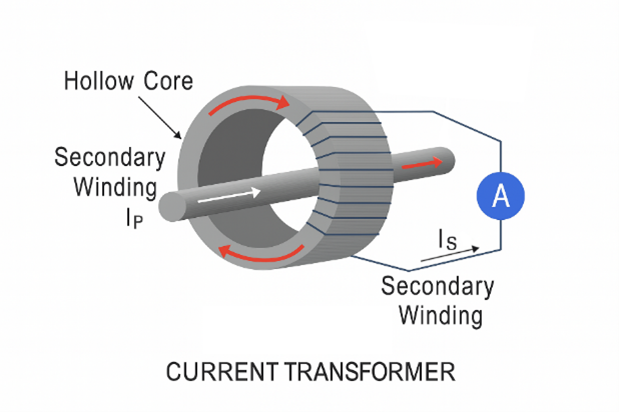
Figure 1: Basic Structure of a CT
Figure 1 illustrates the operating principle of a CT. Based on the turns ratio, changes in the primary current Ip are reflected as Is on the secondary side, which can be used for sensing. A shunt resistor generating an output voltage proportional to the primary current can be employed to monitor the output current. This provides isolation, minimal losses, a simple operating principle, and a voltage output suitable for current sensors without requiring additional amplification. An analog-to-digital converter (ADC) may be capable of directly sampling the output voltage.
The primary current reduction ratio is expressed by the CT ratio. The accuracy of a current transformer is measured by its CT accuracy class (sometimes called the CT rating or CT grade). Based on their accuracy class, CTs fall into two categories: metering accuracy CTs and protection accuracy CTs. Metering accuracy CTs are designed to be highly accurate at all current ratings, even at very low currents. They are evaluated for specific common loads. Due to their high accuracy, utility companies typically use these CTs to evaluate usage for billing purposes. Protective accuracy CTs have lower accuracy than metering accuracy CTs. They are designed to operate at the minimum accuracy level required for equipment protection.
Current transformers are frequently used in power conversion applications due to their low cost and ability to generate output signals directly compatible with analog-to-digital converters. They also play a vital role in power distribution networks operating at 50/60 Hz line frequencies.
These hollow coils are flexible and wrapped around conductors. Changes in the magnetic field induced by the current Ip flowing through the conductor generate a voltage proportional to the rate of change of current. Rogowski coils are primarily used for measuring alternating current, particularly in high-frequency applications.
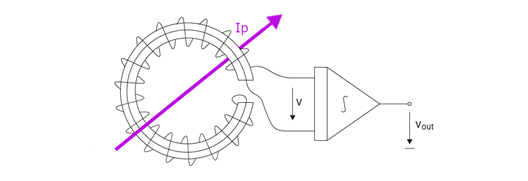
Figure 2: Schematic Diagram of the Rogowski Coil Principle
Figure 2 shows a schematic diagram of the Rogowski coil principle. The derivative of the primary current determines the voltage generated. To achieve the desired current sensing, an integrator is required at the output.
The sensitivity of a Rogowski coil is reduced because current transformers cannot use cores with high magnetic permeability. The key advantage of a Rogowski coil is its inherent linearity and absence of saturation. Rogowski coils can be used to detect currents in power distribution systems, short-circuit testing systems, electromagnetic emitters, slip-ring induction motors, and lightning testing facilities. Pricing is comparable to current transformers.
Current generating static magnetic fields is difficult to detect using Faraday’s law of induction. Conversely, magnetic field sensors can identify both static and moving magnetic fields. They serve as an ideal alternative for current sensing.
These sensors operate on the Hall effect principle, which states that a potential difference forms across a conductor when a magnetic field is applied perpendicular to its cross-section. The direction of the induced electromotive force (EMF) perpendicular to both the current and magnetic field can be determined using the right-hand rule. The magnitude of this EMF and the relative angle between current and magnetic field determine the composite vector voltage, which is proportional to the Hall constant. The magnetic field is generated by the current being measured, producing an analyzable voltage.
Signal conditioning is required to make the output usable in most applications. Signal conditioning electronics typically require amplifier stages and temperature compensation. Differential amplifiers with these characteristics can be easily combined with Hall elements using standard bipolar transistor technology. Temperature compensation is also readily achievable. Figure 3 shows a typical design for a Hall-effect current sensor.
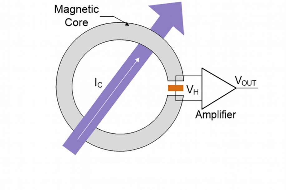
Figure 3: Typical Applications of Open-Loop Hall Current Sensors
Hall effect sensors are widely used in various applications, including power conversion systems, welding equipment, motor drives, radar equipment, and the electrolysis industry.
These magnetic-field-based current sensors are extensively used in both closed-loop and open-loop applications.
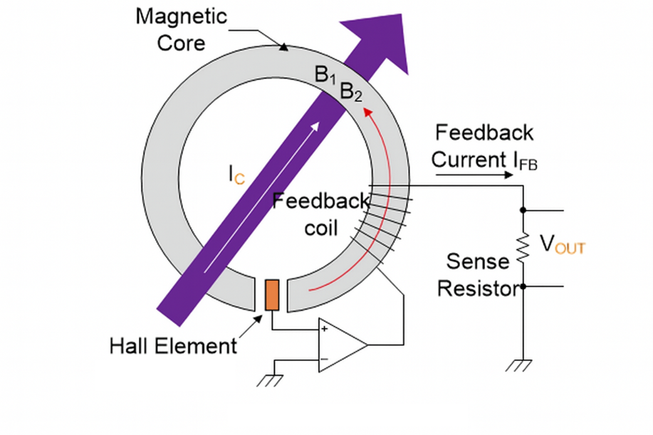
Figure 4: Typical Application of Closed-Loop Hall Current Sensor
The magnetic flux generated by the primary current IP is balanced by a complementary magnetic flux produced by the drive current in the secondary winding. The Hall element and associated electronic circuitry generate a secondary (compensating) current that perfectly corresponds to the primary current.
A basic fluxgate sensor utilizes the nonlinear relationship between the magnetic field H and magnetic flux density B in magnetic materials, which causes a change in the material’s magnetic permeability.
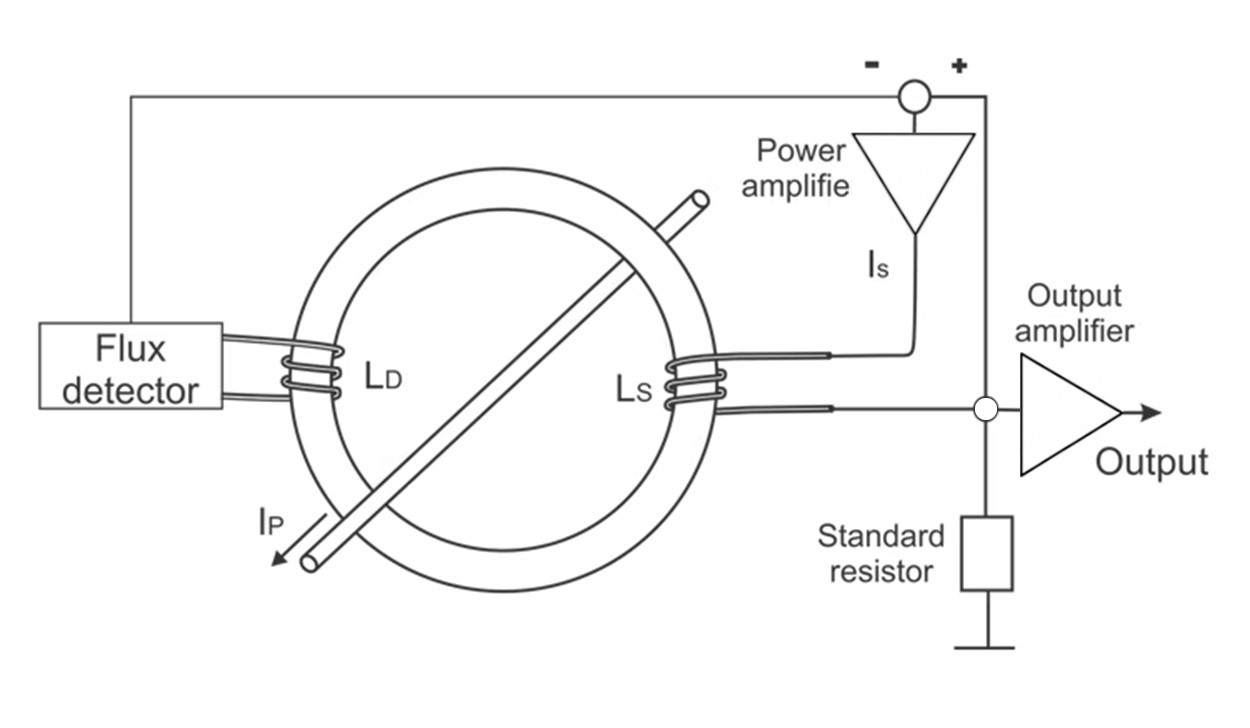
Figure 5: Basic schematic of fluxgate current sensor
Figure 5 illustrates a simple design for a fluxgate sensor used to sense current Ip. Two windings are mounted on the magnetic core: an excitation winding and a pickup winding. The excitation winding is coupled to a sinusoidal current source that generates the excitation magnetic field. Consequently, a voltage is induced in the pickup winding, which can then be utilized for sensing. Given that the external magnetic field is small relative to the excitation field, the peak of the output voltage is proportional to the external field and can be used to quantify it.
Due to their high cost and limited area, isolated fluxgate sensors primarily hold commercial value in high-precision applications. Because of their high accuracy, fluxgate sensors are used in calibration systems, diagnostic systems, laboratory equipment, and medical systems.
When selecting a current sensor for a specific application or project, several factors must be considered to ensure optimal performance and compatibility. Key variables to evaluate include:
Table 1 shows key performance metrics for various sensors.
| Type | Bandwidth | DC Capable | Accuracy | Thermal drift [ppm/K] | Isolated | Range | Power Loss | Relative Cost |
| Current Transformer | kHz-MHz | No | 0.1%-1% | <100 | Yes | A-kA | mW | Low |
| Rogowski Coil | kHz-MHz | No | 0.2%-5% | 50-300 | Yes | A-MA | mW | Moderate |
| Hall Effect open-loop | kHz | Yes | 0.5%-5% | 50-1000 | Yes | A-kA | mW | Moderate |
| Hall Effect closed-loop | kHz | Yes | 0.2%-1% | 50-500 | Yes | A-kA | mW | Moderate |
| Fluxgate | kHz | Yes | 0.001%-0.5% | <50 | Yes | mA-kA | mW-W | High |
The main application fields of current sensors
These are just some applications of current sensors. Due to their adaptability and significance in controlling current, they are key components in various applications across many industries.
Current sensors play a crucial role in various electrical and electronic systems, and thus they are an important component of numerous applications in many industries. This page introduces the useful and prominent aspects of current sensors, such as types, selection criteria, performance comparisons, and common applications.


Copyright © 2024 PowerUC Electronics Co.


