
The magnetic core serves as the “sensing framework” of a current sensor; it concentrates the magnetic field generated by the current in the conductor and transmits it to the Hall effect sensor, coil, or magnetoresistive element for detection.
The quality of the magnetic core directly affects the sensor’s accuracy, linearity, temperature drift, saturation resistance, and frequency response.
Silicon steel is one of the fundamental soft magnetic materials. To reduce eddy current losses, 1% to 5% silicon is added to iron to increase resistivity.
Permalloy is a nickel-iron alloy with extremely high initial permeability and extremely low coercivity.
Ferrite is a type of ceramic magnetic material with extremely high resistivity.
Nanocrystalline materials are manufactured through rapid solidification technology and possess extremely fine grain structures, combining the advantages of silicon steel and permalloy.
| Characteristic | Silicon Steel | Permalloy | Ferrite | Nanocrystalline |
| Saturated magnetic field (Bs) | ~2.0T | ~0.8T | ~0.4T | ~1.2T |
| Initial permeability | Normal | Extremely high | Low | High |
| Frequency response | <1kHz | DC–100kHz | 50Hz–5MHz | DC–200kHz |
| Temperature stability | Good | Fair | Poor | Excellent |
| Linearity | Fair | Excellent | Fair | Good |
| Relative cost | Low | High | Very low | Medium |
PowerUC’s SCT series split-core current transformers are designed for scenarios such as power monitoring, energy management, smart power distribution, and IoT devices. Their core advantage is installation without disconnecting the wiring, while covering a wide range from 1A to 1000A, suitable for various applications from residential to industrial use.
All models feature a split-core design, allowing for snap-on installation without power interruption, making them ideal for retrofit projects and rapid on-site deployment.
The SCT series offers a wide range of specifications, from Φ6mm, Φ10mm, Φ13mm, Φ16mm, Φ24mm, Φ36mm, and Φ52mm to large windows of 80×80mm, 160×80mm, and 220×80mm, covering everything from fine wires to large busbars.
Supported by different models:
DC Output (Built-in Rectification)
The reason for the prevalence of the 2.5V ±0.625V and 2.5V ±2V output ranges for Hall-effect open-loop current sensors
is based on their principle of operation, supply voltage, and optimized design for interfacing with subsequent analog-to-digital converters (ADCs).
The technical reasons behind these standard output ranges are explained in detail below.
2.5V is the standard output voltage for Hall effect current sensors in a zero current (or static) state, often referred to as
Quiescent Output Voltage.
Unipolar Power Supply: Most modern Hall effect current sensors are designed to be powered by a unipolar 5V supply.
Center Point Setting: To measure bi-directional currents (forward and reverse), the sensor’s zero-current output must be set at half the supply voltage VCC, i.e., 5V / 2 = 2.5V.
Mechanism of Operation: The output voltage rises from 2.5V when current flows in the forward direction and falls from 2.5V when current flows in the reverse direction.
This design ensures that the entire output range can represent positive and negative currents in a single-supply system without the need for a negative voltage.
2.5V ±0.625V corresponds to an output span of 1.875V to 3.125V (total 1.25V).
The selection of this range is closely related to the optimized interface of the ADC and the system accuracy.
ADC Interface: Many microcontrollers (MCUs) and DSPs use 3.3V for I/O voltages and ADC reference voltage (VREF).
Optimizing the ADC Dynamic Range: Sensor designers avoid using the full 0V–5V range to prevent saturation.
The signal is limited to within 3.3V for optimal resolution on a 3.3V ADC.
Advantage of 1.25V Span: A ±0.625V range offers safety margins, prevents clipping, and maintains high linearity in 3.3V systems.
ADC Resolution: This span can be matched to ADC resolutions (e.g., 10-bit or 12-bit) to minimize quantization error at rated current.
2.5V ±2V corresponds to 0.5V–4.5V (total span 4V). This range maximizes signal dynamic range and improves noise immunity.
Close to Rail-to-Rail: The 0.5V–4.5V range covers nearly the entire usable range on a 5V supply.
Higher Sensitivity: With a 4V swing, sensitivity (mV/A) and signal-to-noise ratio (SNR) are improved, enhancing measurement precision.
Retention Margin: A 0.5V headroom at both ends avoids nonlinear saturation near 0V and 5V under extreme conditions.
These two output ranges represent different design trade-offs between accuracy/compatibility and
dynamic range/noise immunity for Hall-effect current sensors.
| Feature | 2.5V ±0.625V | 2.5V ±2V |
|---|---|---|
| Span | 1.25V (1.875V–3.125V) | 4V (0.5V–4.5V) |
| Design Goal | Optimize compatibility with 3.3V ADC systems and provide safety margins | Maximize signal dynamic range and signal-to-noise ratio (SNR) |
| Sensitivity | Low | High |
| Application Scenarios | Microcontroller systems with 3.3V supply/reference voltage and high accuracy requirements | Systems requiring high noise immunity or 5V ADC reference operation |
Current sensors are critical components in various electrical and electronic systems, ensuring the safe and efficient operation of equipment and installations. In this article, we will explore current sensors, including their types, variables to consider when selecting a current sensor, performance comparisons, and applications.
We can classify current sensors based on the fundamental physical concepts that constitute them. These concepts encompass Ohm’s Law, Faraday’s Law of Induction, magnetic fields, and optical sensing. Using this framework, we will now introduce several common types of current sensors.
Faraday’s Law of Induction states that the total electromotive force (emf) generated in a closed circuit is proportional to the rate of change of total magnetic flux through the circuit over time. This principle is widely applied in current sensing devices. Two common sensing devices based on Faraday’s law are current transformers (CTs) and Rogowski coils. When electrical isolation is required for safety reasons, these sensors automatically provide the necessary separation between the measured current and the output signal. This makes them highly valuable for existing detection equipment.
A CT consists of a primary winding (typically a single loop), a core, and a secondary winding. It serves as an effective sensor for measuring high alternating currents. Thus, large primary currents can be converted into smaller secondary currents. This device requires no additional drive circuitry as it is inherently passive. Another key feature is its ability to monitor extremely high currents while consuming minimal power. However, the ferrite material used in the core may saturate under extremely high primary currents or currents with substantial DC components, leading to signal distortion. Another issue is that once magnetized, the core develops hysteresis, which degrades accuracy unless it is demagnetized again. Furthermore, since their fundamental principle relies on detecting changes in magnetic flux which is proportional to current changes they cannot detect DC currents in a standard manner.
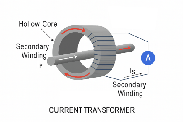
Figure 1: Basic Structure of a CT
Figure 1 illustrates the operating principle of a CT. Based on the turns ratio, changes in the primary current Ip are reflected as Is on the secondary side, which can be used for sensing. A shunt resistor generating an output voltage proportional to the primary current can be employed to monitor the output current. This provides isolation, minimal losses, a simple operating principle, and a voltage output suitable for current sensors without requiring additional amplification. An analog-to-digital converter (ADC) may be capable of directly sampling the output voltage.
The primary current reduction ratio is expressed by the CT ratio. The accuracy of a current transformer is measured by its CT accuracy class (sometimes called the CT rating or CT grade). Based on their accuracy class, CTs fall into two categories: metering accuracy CTs and protection accuracy CTs. Metering accuracy CTs are designed to be highly accurate at all current ratings, even at very low currents. They are evaluated for specific common loads. Due to their high accuracy, utility companies typically use these CTs to evaluate usage for billing purposes. Protective accuracy CTs have lower accuracy than metering accuracy CTs. They are designed to operate at the minimum accuracy level required for equipment protection.
Current transformers are frequently used in power conversion applications due to their low cost and ability to generate output signals directly compatible with analog-to-digital converters. They also play a vital role in power distribution networks operating at 50/60 Hz line frequencies.
These hollow coils are flexible and wrapped around conductors. Changes in the magnetic field induced by the current Ip flowing through the conductor generate a voltage proportional to the rate of change of current. Rogowski coils are primarily used for measuring alternating current, particularly in high-frequency applications.
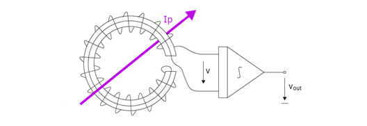
Figure 2: Schematic Diagram of the Rogowski Coil Principle
Figure 2 shows a schematic diagram of the Rogowski coil principle. The derivative of the primary current determines the voltage generated. To achieve the desired current sensing, an integrator is required at the output.
The sensitivity of a Rogowski coil is reduced because current transformers cannot use cores with high magnetic permeability. The key advantage of a Rogowski coil is its inherent linearity and absence of saturation. Rogowski coils can be used to detect currents in power distribution systems, short-circuit testing systems, electromagnetic emitters, slip-ring induction motors, and lightning testing facilities. Pricing is comparable to current transformers.
Current generating static magnetic fields is difficult to detect using Faraday’s law of induction. Conversely, magnetic field sensors can identify both static and moving magnetic fields. They serve as an ideal alternative for current sensing.
These sensors operate on the Hall effect principle, which states that a potential difference forms across a conductor when a magnetic field is applied perpendicular to its cross-section. The direction of the induced electromotive force (EMF) perpendicular to both the current and magnetic field can be determined using the right-hand rule. The magnitude of this EMF and the relative angle between current and magnetic field determine the composite vector voltage, which is proportional to the Hall constant. The magnetic field is generated by the current being measured, producing an analyzable voltage.
Signal conditioning is required to make the output usable in most applications. Signal conditioning electronics typically require amplifier stages and temperature compensation. Differential amplifiers with these characteristics can be easily combined with Hall elements using standard bipolar transistor technology. Temperature compensation is also readily achievable. Figure 3 shows a typical design for a Hall-effect current sensor.
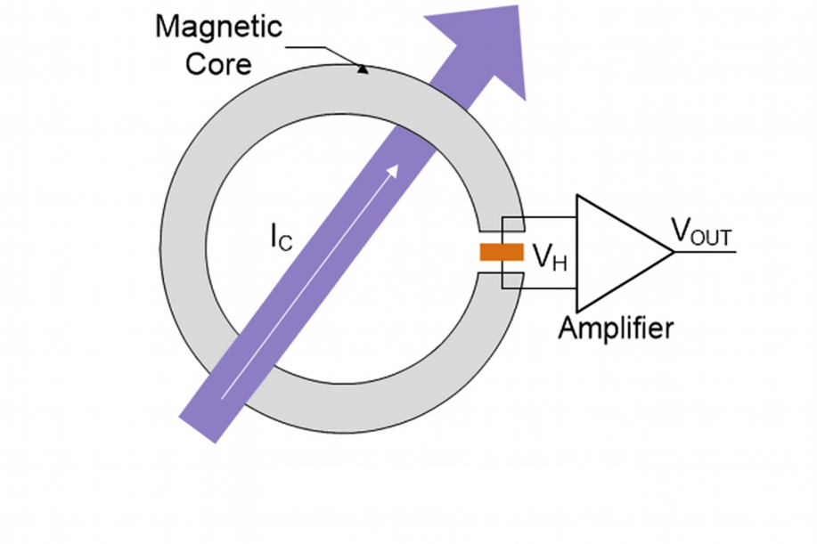
Figure 3: Typical Applications of Open-Loop Hall Current Sensors
Hall effect sensors are widely used in various applications, including power conversion systems, welding equipment, motor drives, radar equipment, and the electrolysis industry.
These magnetic-field-based current sensors are extensively used in both closed-loop and open-loop applications.
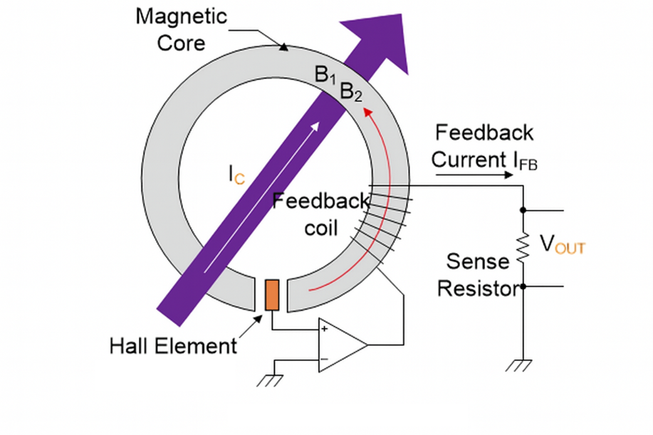
Figure 4: Typical Application of Closed-Loop Hall Current Sensor
The magnetic flux generated by the primary current IP is balanced by a complementary magnetic flux produced by the drive current in the secondary winding. The Hall element and associated electronic circuitry generate a secondary (compensating) current that perfectly corresponds to the primary current.
A basic fluxgate sensor utilizes the nonlinear relationship between the magnetic field H and magnetic flux density B in magnetic materials, which causes a change in the material’s magnetic permeability.
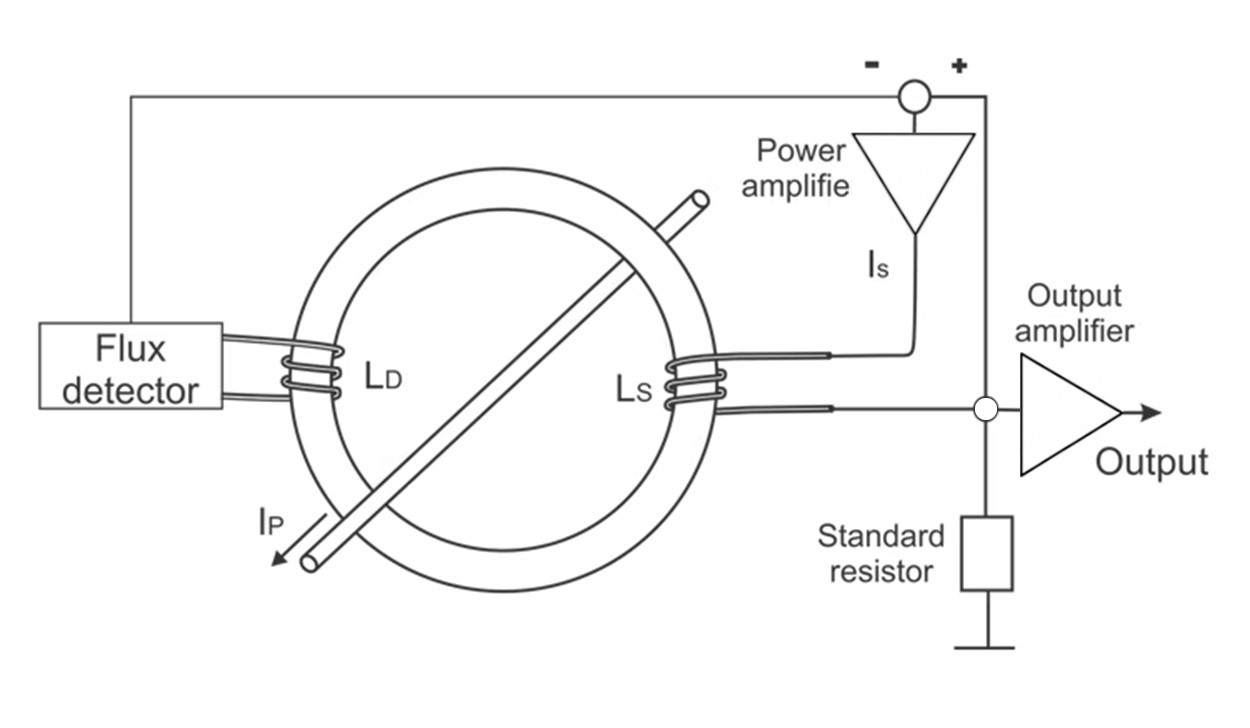
Figure 5: Basic schematic of fluxgate current sensor
Figure 5 illustrates a simple design for a fluxgate sensor used to sense current Ip. Two windings are mounted on the magnetic core: an excitation winding and a pickup winding. The excitation winding is coupled to a sinusoidal current source that generates the excitation magnetic field. Consequently, a voltage is induced in the pickup winding, which can then be utilized for sensing. Given that the external magnetic field is small relative to the excitation field, the peak of the output voltage is proportional to the external field and can be used to quantify it.
Due to their high cost and limited area, isolated fluxgate sensors primarily hold commercial value in high-precision applications. Because of their high accuracy, fluxgate sensors are used in calibration systems, diagnostic systems, laboratory equipment, and medical systems.
When selecting a current sensor for a specific application or project, several factors must be considered to ensure optimal performance and compatibility. Key variables to evaluate include:
Table 1 shows key performance metrics for various sensors.
| Type | Bandwidth | DC Capable | Accuracy | Thermal drift [ppm/K] | Isolated | Range | Power Loss | Relative Cost |
| Current Transformer | kHz-MHz | No | 0.1%-1% | <100 | Yes | A-kA | mW | Low |
| Rogowski Coil | kHz-MHz | No | 0.2%-5% | 50-300 | Yes | A-MA | mW | Moderate |
| Hall Effect open-loop | kHz | Yes | 0.5%-5% | 50-1000 | Yes | A-kA | mW | Moderate |
| Hall Effect closed-loop | kHz | Yes | 0.2%-1% | 50-500 | Yes | A-kA | mW | Moderate |
| Fluxgate | kHz | Yes | 0.001%-0.5% | <50 | Yes | mA-kA | mW-W | High |
The main application fields of current sensors
These are just some applications of current sensors. Due to their adaptability and significance in controlling current, they are key components in various applications across many industries.
Current sensors play a crucial role in various electrical and electronic systems, and thus they are an important component of numerous applications in many industries. This page introduces the useful and prominent aspects of current sensors, such as types, selection criteria, performance comparisons, and common applications.
In modern electrical and electronic systems, voltage and current sensors play a crucial role. As core components for functions such as power system monitoring, industrial automation, smart home systems, and renewable energy management, these sensors convert voltage or current signals into standardized, measurable, recordable, and controllable signals, providing accurate data support for various applications. This article will delve into the basic principles, main types, performance characteristics, and differences between voltage and current sensors, and analyze their wide-ranging applications in various fields.
A voltage sensor is a device capable of detecting voltage values in a circuit and converting these values into measurable electrical signals. Typically, these signals are current or voltage outputs proportional to the original voltage.
This type of sensor is very important in many places, such as power system monitoring, battery management, industrial process control, and consumer electronics. They ensure that the equipment operates within a safe voltage range and also provide real-time data, facilitating our analysis and control.
The basic principle of a voltage sensor is based on Ohm’s law and electromagnetic induction. The most common types of voltage sensors include:
1. Resistance voltage divider type: This is the simplest and most common type of voltage sensor. It uses two or more resistors connected in series to share the voltage and infers the total voltage by measuring the voltage drop across one of the resistors. This method is suitable for measuring DC and low-frequency AC voltages, but the high-frequency response is limited by parasitic capacitance and inductance.
2. Transformer type (PT/VT) : Voltage transformers (PT) or voltage transmitters (VT) are mainly used in high-voltage AC circuits to proportionally reduce high voltages to a safe and measurable level. They are based on the principle of electromagnetic induction and achieve voltage isolation and conversion through magnetic coupling between the primary coil and the secondary coil. This type of sensor features excellent isolation performance and high precision, and is often used for measurement and protection in power systems.
3. Hall Effect type: Although Hall effect sensors are mainly used for current measurement, some designs can also be used for voltage measurement, especially in situations that require high isolation or the measurement of DC high voltage. It measures indirectly by measuring the magnetic field strength
Voltage, usually requires converting voltage into current or utilizing the magnetic field generated by voltage.
4. Fluxgate type: Fluxgate sensors measure direct current or alternating current by utilizing the saturation characteristics of magnetic core materials in alternating magnetic fields. It features high sensitivity, high precision and good linearity, and is often used for weak current measurement and high-precision applications.
5. Photoelectric isolation type: This type of sensor uses photoelectric conversion technology to achieve electrical isolation between the input and output. The input electrical voltage is converted into an optical signal by the optical transmitter, and the optical signal is then converted into an electrical signal by the optical receiver for output. This method provides extremely high isolation voltage and anti-interference capability, and is suitable for harsh electromagnetic environments.
The PowerUC website offers a variety of principle voltage sensor products, such as Hall effect type, voltage sensor, fluxgate type, and photoelectric isolation type. These products usually have the following characteristics:
Input type: Supports AC (AC) and DC (DC) inputs.
Output type: Instantaneous or true RMS output is provided. The output signal can be electrical voltage (such as ±5V, 2.5±0.625V) or current (such as 25mA, 0-20mA, 4-20mA).
Rated input voltage: Covering a wide range from 50V to 10,000V, it meets the application requirements of different voltage levels. Power supply voltage: Supports multiple power supplies including ±12V, ±15V, 3.3V, 5V, 12V, 24V, etc.
Connection and installation methods: including connection methods such as Screw Terminal, Pins, Cable, etc., as well as installation methods such as Plate, PCB installation, DIN Rail, etc.
It is widely applied in industrial control, power monitoring, new energy power generation and other fields. Its high precision and reliability ensure the stable operation of the system.
A current sensor is a device used to detect the intensity of current in a circuit and convert it into a measurable electrical signal. Similar to voltage sensors, current sensors are also widely used in fields such as power, industrial automation, automotive electronics, and medical equipment. They are crucial for overload protection, energy consumption monitoring, fault diagnosis and system optimization.
The measurement principles of current sensors are diverse, mainly including:
1. Shunt type: A shunt is a low-resistance resistor with an exact known resistance value. When current flows through a shunt, according to Ohm’s Law (V=IR), a voltage drop proportional to the current will be generated across its terminals. By measuring this voltage drop, the current flowing through the shunt can be calculated. The shunt has a simple structure and low cost, but it will introduce certain power consumption and voltage drop, and does not provide electrical isolation.
2. Current transformer type (CT) : Current transformers are mainly used to measure large alternating currents. It utilizes the principle of electromagnetic induction to proportionally convert a large current into a small one. The measured current flows through the primary coil of the transformer and induces a proportional current in the secondary coil. Current transformers offer excellent electrical isolation and are widely used in measurement and protection in power systems.
3. Hall Effect type: Hall effect sensors are based on the Hall effect principle. When current flows through a conductor, a magnetic field is generated around it. When a Hall sensor is placed in a magnetic field, it generates a Hall voltage proportional to the strength of the magnetic field. The current can be indirectly measured by measuring the Hall voltage. Hall effect sensors can measure both DC and AC currents and provide electrical isolation, making them suitable for wide current ranges and high-precision measurements.
4. Fluxgate type: Fluxgate sensors measure direct current or alternating current by utilizing the saturation characteristics of magnetic core materials in alternating magnetic fields. It features high sensitivity, high precision and good linearity, and is often used for weak current measurement and high-precision applications.
5. Rogowski Coil type: A Rogowski coil is an air-core coil used for measuring alternating current. It outputs a voltage signal through the change in magnetic flux caused by the induced current, and this voltage is proportional to the rate of change of the current. Roche coils have the advantages of no magnetic saturation, wide frequency response, and high isolation, and are particularly suitable for measuring large currents and high-frequency currents.
The PowerUC website offers a variety of current sensor products based on different principles, such as Hall effect type, fluxgate type, and Roche coil type current sensors. These products usually have the following characteristics:
Input type: Supports AC (AC) and DC (DC) inputs.
Output type: Instantaneous, true RMS, Digital Signal or TRMS output is provided. The output signal can be voltage (such as ±4V, 2.5±0.625V) or current (such as 50mA, 25mA, 4-20mA).
Rated input current: Covering a wide range from 3A to 5000A, it meets the application requirements of different current levels. Power supply voltage: Supports multiple power supplies such as ±12V, ±15V, 3.3V, and 5V.
Connection and installation methods: Including connection methods such as Cable, Quick plug, Pins, Screw Terminal, as well as installation methods such as Plate, PCB mounting, and Free Hanging.
For instance, PowerUC’s HSTS series current sensors are widely used in industrial control, motor drive, battery management systems and other fields. Their high precision and reliability ensure the stable operation of the system.
Although both voltage sensors and current sensors are used to measure electrical parameters, they differ significantly in terms of the objects they measure, working principles, application scenarios, and performance characteristics.
| Features | Voltage sensor | Current sensor |
|---|---|---|
| Measurement objects | The potential difference (voltage) between two points in a circuit. | The amount of electric charge flowing through a conductor (current). |
| Basic Principles | Voltage divider, electromagnetic induction (current transformer), Hall effect (partial), fluxgate,opto-isolation | Shunt resistor, electromagnetic induction (current transformer), Hall effect, fluxgate sensor, Rogowski coil |
| Connection Method | Typically connected in parallel across the terminals of the circuit being measured | Alternatively, connected in series within the circuit, or using an inductive method (e.g., current transformer, Hall effect) for non-contact measurement |
| Isolation Characteristics | Current transformers, opto-isolators, Hall effect sensors, and fluxgate sensors provide electrical isolation; resistive voltage dividers typically do not. | Current transformers, Hall effect sensors, fluxgate sensors, and Rogowski coils provide electrical isolation; shunt resistors do not. |
| Power Consumption | High internal impedance results in low power consumption, minimizing the impact on the measured circuit. | Shunt resistors have power dissipation and voltage drop; other types of resistors have relatively lower power consumption. |
| Application Scenarios | Power grid voltage monitoring, battery voltage management, power supply output monitoring, equipment over/under voltage protection | Motor current monitoring, load current detection, ground fault protection, energy consumption metering, battery charging and discharging management |
| Key challenges | High-voltage isolation, measurement accuracy, frequency response | Large current measurement, high precision, wide frequency response, and interference immunity |
The measurement purposes are different: voltage sensors focus on potential differences, while current sensors focus on the flow of electric charges. This determines the fundamental differences in their connection methods and measurement principles in the circuit.
The connection methods are different: Voltage sensors are usually connected in parallel in the circuit to measure the potential difference between two points. Current transducers are usually connected in series in circuits to measure the current flowing through conductors or to induce the magnetic field generated by the current through non-contact methods (such as transformers, Hall effect).
Isolation requirements: In high-voltage or strong electromagnetic interference environments, electrical isolation is of vital importance. Both transformer and photoelectric isolation technologies are used to provide isolation in both types of sensors, but current sensors, due to the characteristics of their measurement methods, are usually easier to achieve high isolation.
Power consumption and voltage drop: Shunt type current sensors introduce certain power consumption and voltage drop, which need to be particularly considered in low-power or high-precision applications. Due to its high input impedance, voltage sensors usually have a relatively small impact on the circuit under test.
In practical applications, voltage sensors and current sensors often need to work in coordination to provide comprehensive and accurate monitoring data for power systems or electronic devices. For instance, in electric metering, both voltage and current need to be measured simultaneously to calculate power and energy.
To gain a deeper understanding of voltage and current sensors, it is necessary for us to explore their core working principles in detail. Although it was briefly mentioned in the previous text, this section will provide a more specific description of the mechanism.
A voltage sensor converts voltage signals into measurable electrical signals. Its working principle mainly relies on the following mechanisms:
1 Principle of voltage division by resistance
Mechanism:This is the most intuitive method for voltage measurement. A voltage divider circuit is formed by connecting two or more resistors in series across the two terminals of the voltage to be measured. According to Ohm’s Law, the voltage drop across each resistor is directly proportional to its resistance value. By precisely measuring the voltage across one of the resistors and combining it with the proportional relationship of the resistors, the total electrical voltage can be calculated. For instance, if R1 and R2 are connected in series, the total voltage V = V_R1 + V_R2, and V_R2 = V * (R2 / (R1 + R2)). By measuring V_R2, V can be inferred in reverse.
Features: Simple structure, low cost, suitable for DC and low-frequency AC voltage measurement. However, it does not provide electrical isolation, and in high-frequency environments, the parasitic capacitance and inductance of the resistance can affect the measurement accuracy.
2. Electromagnetic Induction Principle (Voltage Transformer) :
Mechanism: Voltage transformers (PT/VT) utilize the principle of transformers. The high-voltage side (primary coil) is connected in parallel with the high-voltage circuit under test, and the low-voltage side (secondary coil) is connected to the measuring instrument. When high voltage passes through the primary coil, an alternating magnetic field is generated, which induces a proportional low voltage in the secondary coil. By precisely measuring the turns ratio, the measured high voltage can be safely reduced proportionally to the standard measurement range (such as 100V or 110V).
Features: It provides high-voltage isolation, has high measurement accuracy, and is suitable for high-voltage measurement and protection in power systems. It is mainly used for AC voltage measurement.
3. Hall Effect Principle (for some voltage sensors):
Mechanism: Although Hall effect sensors are mainly used for current measurement, voltage measurement can also be achieved by converting voltage to current (for example, through a known resistor), or by indirectly influencing the magnetic field with the electric field generated by the voltage. In this case, the Hall element senses the magnetic field intensity and generates a Hall voltage proportional to the magnetic field intensity. Through calibration, the Hall voltage can be correlated with the original voltage.
Features: It offers electrical isolation and is suitable for both DC and AC voltage measurement, especially having advantages in high-voltage or high-isolation applications.
4. Principle of photoelectric isolation:
Mechanism: The photoelectric isolation voltage sensor achieves electrical isolation through light signals as an intermediate medium. The input voltage signal drives a light-emitting diode (LED) to emit a light signal. After passing through an insulating medium, the light signal is received by a photosensitive receiver (such as a phototransistor) and converted into an electrical signal proportional to the original voltage for output. Since the transmission of optical signals does not involve electrical contact, high-voltage isolation between the input and output is achieved.
Features: It offers extremely high electrical isolation and anti-electromagnetic interference capabilities, with a fast response speed, and is suitable for harsh electromagnetic environments and high-voltage applications.
Current sensors convert current signals into measurable electrical signals. Their working principle mainly relies on the following mechanisms:
1. Principle of the shunt:
Mechanism: The shunt is a precision resistor with a known and very small resistance value. When the current to be measured flows through the shunt, according to Ohm’s Law (V = I * R), a tiny voltage drop proportional to the current will be generated across the shunt. By measuring this voltage drop and combining it with the resistance value of the shunt, the current flowing through the circuit can be calculated.
Features: Simple structure, low cost, suitable for both DC and AC current measurement. However, since it is connected in series in the circuit, it will introduce certain power consumption and voltage drop, and does not provide electrical isolation.
2. Electromagnetic Induction Principle (Current Transformer):
Mechanism: The current transformer (CT) utilizes the principle of a transformer. The measured large current flows through the primary coil (usually the wire passing through the center hole of the transformer), generating magnetic flux in the iron core. This magnetic flux induces a proportional small current in the secondary coil. By precisely measuring the turns ratio, the measured large current can be safely reduced proportionally to the standard measurement range (such as 5A or 1A).
Features: It offers electrical isolation, has high measurement accuracy, and is suitable for large current measurement and protection in power systems. It is mainly used for alternating current measurement.
3. Principle of Hall Effect:
Mechanism: When current flows through a conductor, a magnetic field is generated around it. The Hall effect current sensor places the Hall element in this magnetic field. According to the Hall effect, when current passes through a Hall element and is in a magnetic field perpendicular to the current direction, a magnetic field intensity and current intensity will be generated between the two sides of the Hall element
Hall voltages that are all proportional. By measuring this Hall voltage, the magnitude of the current being measured can be calculated. Closed-loop Hall sensors also counteract magnetic fields through feedback current, further enhancing accuracy and linearity.
Features: It can measure both DC and AC currents, provides electrical isolation, has a fast response speed, and is suitable for wide current ranges and high-precision measurements.
4. Fluxgate Principle:
Mechanism: Fluxgate sensors utilize the nonlinear magnetization characteristics of magnetic core materials in an alternating magnetic field. It usually contains a magnetic core that is easily saturated and an excitation coil. When the magnetic field generated by the measured direct current is superimposed on the alternating magnetic field produced by the excitation coil, it will change the saturation point of the magnetic core, thereby affecting the induced voltage waveform of the excitation coil. By detecting the changes in this waveform, direct current can be precisely measured.
Features: High sensitivity, capable of measuring weak direct current, with excellent stability and linearity.
Mechanism: A Rogowski coil is a hollow coil uniformly wound around a non-magnetic skeleton. It generates an induced voltage across the coil by inducing an alternating magnetic field produced by the alternating current being measured. According to Faraday’s law of electromagnetic induction, this induced voltage is directly proportional to the rate of change (dI/dt) of the measured current. In order to obtain the current signal, the induced voltage needs to be integrated.
Features: No magnetic saturation issue, wide frequency response, high isolation, suitable for measuring large currents, high-frequency currents and transient currents.
Voltage sensors and current sensors have extensive applications in modern industry and daily life. They are key components for the normal operation and optimization of many systems.
1. Power System Monitoring and Protection:
Grid voltage monitoring: Real-time monitoring of the voltage level in the transmission and distribution grid to ensure stable operation of the grid and prevent damage to equipment caused by overvoltage or undervoltage.
Generator and transformer protection: Monitor the voltage output of generators and transformers. Once abnormal voltage fluctuations occur, immediately trigger the protection mechanism to prevent equipment damage.
Reactive power compensation: In power systems, voltage sensors are used to detect voltage deviations and guide reactive power compensation devices to make adjustments to improve the power factor of the power grid.
2. Renewable Energy Applications:
Solar inverter: Monitor the output voltage of the solar panel and the input/output voltage of the inverter to ensure the maximum power point tracking (MPPT) efficiency and power quality.
Wind power generation: Monitor the output voltage of wind turbine generators to ensure the stability of grid-connected voltage.
Energy storage system: In battery energy storage systems, voltage sensors are used to monitor the voltage of the battery pack, assess the state of charge (SOC) and state of health (SOH), and prevent overcharging and overdischarging.
3. Industrial Automation and Control:
Power management: Monitor the voltage stability of the power supply for industrial equipment to ensure that the equipment operates at the rated voltage.
Motor control: In frequency converters and servo systems, voltage sensors are used to detect the DC bus voltage and the motor phase voltage to achieve precise control.
Process control: In industries such as chemical engineering and metallurgy, voltage sensors are used to monitor the electrical voltage parameters of key equipment during the production process to ensure process stability.
4. Electric Vehicles and Charging Stations:
Battery Management System (BMS) : Precisely monitors the voltage of each battery cell in the power battery pack of electric vehicles to prevent overcharging, overdischarging and imbalance, and extend battery life.
Charging piles: Monitor the voltage during the charging process to ensure charging safety and efficiency.
5. Consumer Electronics:
Power adapter: Monitors the output voltage to ensure a stable power supply for the device.
Household appliances: Some high-end home appliances integrate voltage monitoring functions to protect the internal circuits.
1. Power System Monitoring and Protection:
Power grid current monitoring: Real-time monitoring of the current load in the transmission and distribution network to prevent overload and optimize power dispatching.
Short-circuit and overload protection: Detect abnormally large currents in the circuit, trigger circuit breakers or fuses to act, and protect equipment and lines.
Fault diagnosis: By analyzing the current waveform and magnitude, diagnose problems such as ground faults and interphase short circuits in the power system.
2. Renewable Energy Applications:
Solar inverter: Monitor the input/output current of the inverter, evaluate the power generation efficiency and power quality.
Wind power generation: Monitor the output current of the wind turbine generator to ensure the stability of the grid-connected current.
Energy storage system: Monitor the charging and discharging current of the battery pack, conduct precise state of charge (SOC) management and battery health assessment.
3. Industrial Automation and Control:
Motor drive and control: Precisely measure motor current, implement advanced control strategies such as vector control and torque control, and enhance motor efficiency and performance.
Load monitoring: Monitor the current consumption of equipment on the production line, determine the operating status of the equipment, and conduct predictive maintenance.
Welding equipment: Precisely control the welding current to ensure welding quality.
4. Electric Vehicles and Charging Stations:
Battery Management System (BMS) : Precisely monitors the charging and discharging current of the power battery pack in electric vehicles, prevents overcurrent, and ensures battery safety.
Charging piles: Monitor charging current to achieve constant current charging and precise control of the charging process.
5. Smart Home and Building Applications:
Energy consumption monitoring: Monitor the real-time electricity current of a household or building to help users understand energy consumption and achieve energy-saving management.
Leakage protection: By detecting leakage current, it promptly cuts off the power supply to prevent electric shock accidents.
6. Medical Devices:
Medical power supply: Monitor the power current of medical equipment to ensure stable operation of the equipment and patient safety.
Diagnostic equipment: In some diagnostic devices, current sensors are used to measure weak biological current signals.
Our company’s Rogowski coil current sensor has withstood the extreme working conditions of high temperature, high dust, and strong electromagnetic interference in the 10KA high current monitoring scenario of the thermal electric furnace in metallurgical enterprises, and has been operating continuously without fault for more than two years.
It is worth mentioning that the product is equipped with a 25-meter-long signal transmission cable, which can stably transmit data in a complex industrial environment.
We are delighted to report yet another successful year exhibiting at PCIM Europe, the leading international exhibition and conference for power electronics. From May 7th to 9th, our team of three – our R&D engineer, global sales supervisor, and business development manager – was on the ground at booth 6-242 in Messe Nuremberg, soaking in the latest trends and connecting with the vibrant power electronics community.
As a yearly fixture in our calendar, PCIM Europe consistently provides an unparalleled platform for us to engage with industry leaders, esteemed colleagues, and both familiar faces among our existing clients and exciting new potential leads. This year was no exception, filled with insightful discussions and valuable networking opportunities.
We actively participated in the pulse of the industry, observing key trends shaping the future of power electronics. Discussions around enhanced efficiency, increased power density, and the crucial role of robust, reliable components in new energy applications were prevalent. It’s clear that the drive towards sustainable and smarter energy solutions continues to accelerate, with innovation in areas like electric vehicle charging and advanced industrial control systems taking center stage.
Our diverse range of products, spanning Rogowski coils, power transformers, leakage current sensors, current sensors, and current transformers, resonated well with attendees. We were particularly pleased with the positive attention and feedback received for our specialized solutions, such as the ZDA13 series leakage current sensors, critical for EV charging safety, and our versatile Rogowski coils, ideal for high-current measurements in demanding environments.
Thank you to everyone who stopped by our booth and engaged with us. The energy and collaborative spirit of PCIM Europe truly embody the innovation within our field. Being there allows us to stay at the forefront of technological advancements and reinforce our commitment to continuous learning and growth.
To get a closer look at our experience and product showcase, be sure to check out the video below! We are already looking forward to our annual return and eagerly anticipate seeing you again at PCIM Europe 2026!


Copyright © 2024 PowerUC Electronics Co.


