A current transformer (CT) operates on the principle of electromagnetic induction, similar to a standard transformer. Its primary purpose is to step down high currents from a power system to a lower, manageable value for metering, protection, and control devices. Here’s a breakdown of the working principle of a current transformer:
1. Basic Construction:
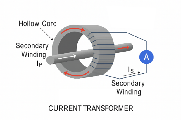
- A CT typically consists of:
- Primary winding: The conductor carrying the high current, which can be a single turn or just the system conductor passing through the CT core.
- Core: Made of ferromagnetic material, it concentrates the magnetic field created by the current in the primary winding.
- Secondary winding: Wound around the core, with many more turns than the primary. This winding connects to meters, relays, or other measurement/protection devices.
2. Working Principle: Electromagnetic Induction:
The CT works based on Faraday’s Law of Electromagnetic Induction, which states that a changing magnetic field within a conductor induces a voltage in another conductor near it.
- Primary Current:
- When high current flows through the primary winding (or conductor), it generates a magnetic field around the primary conductor.
- This magnetic field is concentrated by the CT core and links to the secondary winding.
- Induced Current in the Secondary:
- The varying magnetic field generated by the primary current induces an electromotive force (EMF) in the secondary winding, which causes a current to flow through it.
- The secondary current is proportional to the primary current but reduced by the turns ratio between the primary and secondary windings.
- Turns Ratio:
- The ratio of the number of turns in the secondary winding to the number of turns in the primary winding determines the reduction in current.
- For example, if the primary consists of one turn (a conductor passing through the core), and the secondary has 1000 turns, a primary current of 1000 A would result in a secondary current of 1 A (1000:1 ratio).
3. Operation in a Closed Secondary Circuit:
- The secondary winding must always be closed (either connected to a load or short-circuited) when the primary current is flowing. This allows the magnetic field created by the primary current to induce a proportional current in the secondary.
- The secondary winding is typically connected to low-impedance measuring devices, such as ammeters, relays, or protection systems.
4. Purpose and Applications:
- Current Measurement: CTs reduce the high current in the primary circuit to a smaller, standardized value (e.g., 1 A or 5 A), which can be safely measured by instruments.
- Protection: CTs provide current input to protective relays that trigger circuit breakers in case of overcurrent or fault conditions.
- Isolation: CTs electrically isolate the high-voltage primary circuit from the low-voltage measuring or protective devices for safety.
5. Accuracy Classes:
CTs are designed to operate with high accuracy, so the secondary current is directly proportional to the primary current within a specified accuracy class (e.g., 1% or 0.5% error). Accuracy is critical in both metering and protection applications.
Summary of Working:
- The primary current creates a magnetic field in the CT core.
- This varying magnetic field induces a current in the secondary winding.
- The secondary current is a scaled-down version of the primary current, based on the turns ratio.
- The secondary current can then be measured or used for control/protection purposes.
This allows the safe and accurate measurement of high currents in power systems, protecting both personnel and equipment.