
The HAS series current sensors indicate the magnitude and direction of the measured current through their voltage output signals. Its core feature is that the output signal takes 2.5V as the center point and is offset according to the direction and magnitude of the current on this basis. This design enables the sensor to measure bidirectional current.
For the HAS14Z current sensor, its output voltage range is 2.5V ± 0.625V. This means:
•Zero current (0A): When no current passes through the sensor, the output voltage is 2.5V.
• Forward current: When the current is forward, the output voltage will increase from 2.5V to a maximum of 2.5V + 0.625V = 3.125V.
• Reverse current: When the current is in reverse, the output voltage will decrease from 2.5V to 1.875V, with a minimum of 2.5V – 0.625V = 1.875V.
This range of 2.5V±0.625V usually corresponds to the rated measurement current range of the sensor. For example, for HAS2009, its rated current is ±20A; For HAS4009, its rated current is ±100A.
Through the nominal sensitivity (SN) of the sensor, we can convert the collected voltage signal into the actual current value. The calculation formula is as follows:
IP = (Vout – 2.5V)/SN
Among them:
•IP is the measured current (unit: A)
• Vout is the voltage output by the sensor (unit: V)
•2.5V is the reference voltage at zero current
•SN is the nominal sensitivity of the sensor (unit: V/A or mV/A).
Example:
Suppose the HAS14Z current sensor (SN = 104.2 mV/A or 0.1042 V/A) is used.
•If Vout is measured to be 2.8V: IP = (2.8V – 2.5V) / 0.1042V /A ≈ 2.88A (forward current)
•If Vout is measured to be 2.2V: IP = (2.2V – 2.5V) / 0.1042V /A ≈ -2.88A (reverse current)
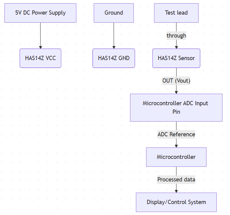
The HAS series current sensors typically have the following pins:
• VCC (+5V): Positive input of sensor power supply, connected to a stable 5V DC power supply.
• GND: The power ground and signal ground of the sensor should be shared with the ground wire of the control system.
• OUT (Vout): Sensor voltage output pin, used for collecting current signals.
Typical wiring diagram (taking microcontrollers as an example) :
Wiring precautions
1). Power supply: Ensure a stable 5V power supply is provided for the sensor. The quality of the power supply directly affects the measurement accuracy.
2). Common ground: The sensor and the microcontroller must share the same ground to avoid measurement errors caused by ground potential differences.
3). Wiring: The wire of the current to be measured should be correctly passed through the measurement hole of the sensor and centered as much as possible to ensure the best measurement effect.
The 2.5V±0.625V voltage output signal of the current sensor is mainly collected through an analog-to-digital converter (ADC). The following are the detailed steps:
1). ADC configuration:
•Select the ADC pin: Connect the OUT pin of the sensor to one of the ADC input pins of the microcontroller.
•Set the reference voltage: Set the reference voltage of the ADC to 5V (if the sensor output range is 0.25V to 4.75V), or select an appropriate reference voltage based on the actual situation. Ensure that the ADC can cover the entire output range of the sensor.
•Set the resolution and sampling rate: Select the resolution (such as 10-bit or 12-bit) and sampling rate of the ADC according to the application requirements. Higher resolution provides more accurate measurements, and a higher sampling rate is suitable for rapidly changing currents.
2). Read the ADC value:
•The digital values of the ADC input pins are periodically read through microcontroller programming.
3). Convert the ADC value to voltage:
•Convert the read digital value to the actual voltage value Vout. For example, for a 10-bit ADC (0-1023) with a 5V reference voltage, the conversion formula is: Vout = (ADC_Value / 1024.0) * 5.0 (unit: V)
4). Calculate the actual current
•Use the following formula to convert the voltage Vout to the actual current IP: IP = (Vout – 2.5V)/SN, where SN is the nominal sensitivity of the sensor (unit: V/A). For instance, the SN of HAS14Z is 0.1042 V/A.
Sample calculation
Suppose the HAS14Z current sensor (SN = 0.1042 V/A) is used.
•If the output voltage Vout measured by the ADC is 2.8V: IP = (2.8V – 2.5V) / 0.1042V /A ≈ 2.88A (forward current)
•If the output voltage Vout measured by the ADC is 2.2V: IP = (2.2V – 2.5V) / 0.1042V /A ≈ -2.88A (reverse current)
By following the above steps, you can accurately collect and calculate the magnitude and direction of the current being measured.
The HAS series closed-loop principle current sensors are widely used in the following fields due to their bidirectional current measurement capability and voltage output characteristics:
• Motor control: Achieve precise speed and torque control for electric vehicles, industrial robots and other equipment.
• Battery Management System (BMS): Monitors the charging and discharging status of the battery to optimize battery health and efficiency.
• Power management: Used in UPS, SMPS, solar inverters, etc., it precisely controls the power flow.
Renewable energy systems: Monitor the current at the connection points between energy storage systems and the power grid to optimize energy conversion.
• Industrial automation: Provides real-time current data for process control, fault diagnosis and safety protection.


Copyright © 2024 PowerUC Electronics Co.


