
In power systems, measuring devices such as electricity meters typically need to be connected to high-voltage or high-current circuits via current transformers (CTs). A common standard is that the interface parameters of electricity meters and the rated secondary current of their matching CTs are almost always 5A (or 1A). This article will delve into the reasons behind this standard and, in conjunction with common parameter markings on electricity meters, explain how to correctly select the matching current transformer.
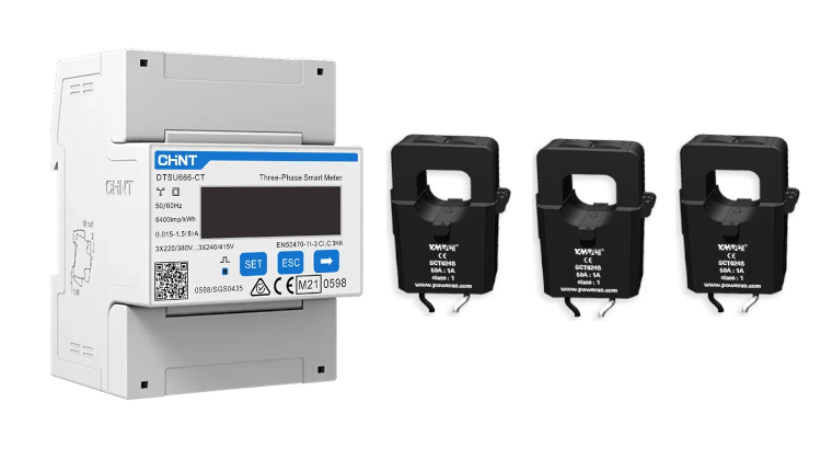
The current transformer parameters supported by the meter are usually marked on the meter, such as 0.25-5(6)A, 0.015-1.5(6)A, 0.25-5(80)A, 0.25-5(100)A, etc. These parameters identify the operating range and technical requirements when connecting to an external CT. These parameters identify the operating range and technical requirements of the meter when connected to an external CT:
Take 0.015-1.5(6)A as an example:
* Starting current (0.015): the minimum current of 15mA that the meter can accurately measure.
* Basic current Ib(1.5):The rated current value of the energy meter is 1.5A, and the accuracy level of the energy meter can be guaranteed when it works under this current.
* Maximum current Imax(6): the maximum current at which the meter can be carried safely and continuously without damage, 6 A. This is covered in the IEC/EN 62053 specification for electricity meters.
Two core principles must be followed in selecting a matching current transformer: secondary current matching and primary current sizing.
The rated secondary current of the CT must match the basic current Ib of the energy meter.
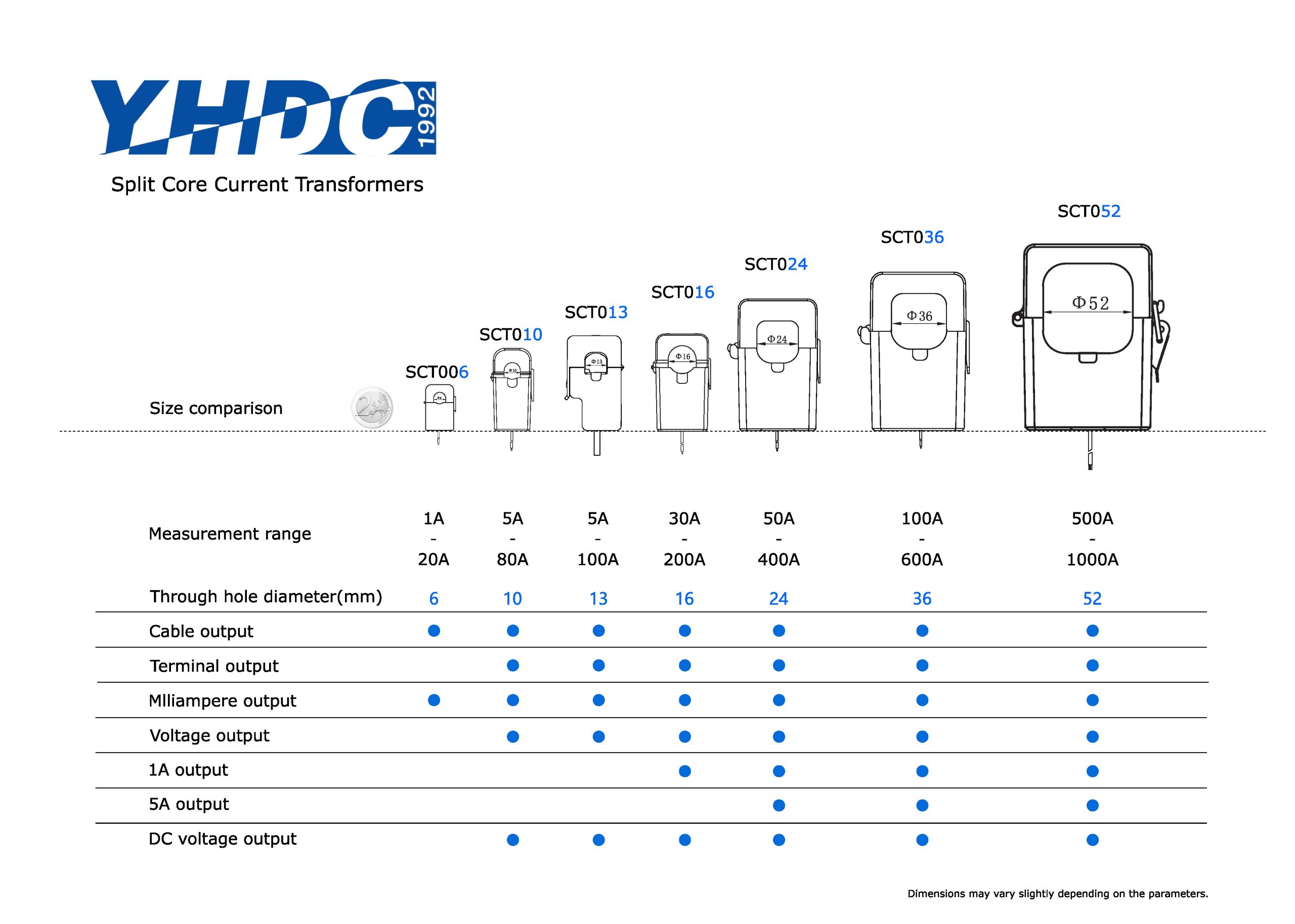
– For meters with parameters 0.25-5(6)A, 0.25-5(80)A, 0.25-5(100)A, you need a current transformer with a 5A rated secondary current.
– For energy meters with parameters 0.015-1.5(6)A (used in specific scenarios although the base current is not 5A/1A standard), you need to equip a CT with a rated secondary current of 1.5A (these are less common and usually follow the 5A or 1A standard).
The rated primary current of the CT (which determines the variable ratio, e.g., 100/5A, 500/5A, 100/1A) should be selected in accordance with the load current of the actual primary circuit. The selection principle is to make the actual load current of normal operation close to the rated primary current of the CT. According to IEC/EN 61869 standard, 1.2 times of the rated primary current is also in line with the nominal accuracy of the product, so the best measurement accuracy can be ensured.
Therefore, for energy meters with parameters of 0.015-1.5(6)A, the best match is a current transformer (CT) with a secondary rated output of 1A.
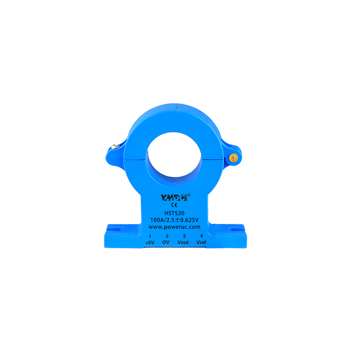
If you are interested in the measurement of small currents and do not have high requirements for measurement accuracy and range, you can also choose a current transformer (CT) with a secondary rated output of 100mA.
Returning to the question at the heart of the article, why has the industry generally adopted 5A or 1A as the standard secondary current for CTs? The reason is a combination of performance, standardization, and safety:
Performance Requirements and Historical Reasons
Early electromechanical energy meters and protective relays required a certain amount of physical energy (power) to actuate the mechanical components. 5A current provided a strong enough signal and power to ensure reliable and accurate operation of these devices. Current signals in the milliamp range are too weak, susceptible to interference and unable to drive older devices.
Standardization and Global Interchangeability
5A is established as the global standard for the power industry, ensuring that devices from different manufacturers and countries are easily compatible and interchangeable, greatly simplifying system design, manufacturing and maintenance.
Balancing Safety and Economy
The core safety objective of the CT is to isolate the high voltage high current circuits from the low voltage measurement circuits. 5A’s relatively low secondary current reduces operational risk. At the same time, the 5A strikes a good balance between cabling costs, wire cross-section requirements and power loss. Where long wiring distances are required, the 1A standard is used to further reduce line losses (1A losses are only 4% of 5A).
In summary, the selection of 5A (or 1A) as the standard secondary current for CTs is the result of engineering practices that optimize performance, cost, historical compatibility and operational reliability.


Copyright © 2024 PowerUC Electronics Co.


