
Current transformers (CTs) are indispensable critical equipment in power systems, undertaking the vital task of proportionally converting high currents on the high-voltage side into low currents on the low-voltage side. They provide accurate and reliable signals for measurement, metering, and relay protection systems. Given their central role in the grid, proper operation and meticulous maintenance directly impact the safety and stability of the entire power system. This paper systematically outlines the core principles for the operation and maintenance of current transformers.
Although current transformers are designed to withstand short-term or long-term operation at 1.2 times the rated current, this does not imply that the risks associated with prolonged overload can be ignored. Sustained overload operation triggers a series of cascading issues that severely impact equipment performance and lifespan.
Reduced Measurement Accuracy: Overloading challenges the linear operating range of CTs. When currents exceed normal limits, significant increases in ratio error and phase angle error occur. This leads to inaccurate meter readings, energy metering deviations, and an inability to accurately reflect the system’s actual load conditions.
Core Saturation and Overheating: During prolonged overload operation, excessive primary-side current causes the core’s magnetic flux density to remain persistently high, potentially reaching saturation. Core saturation prevents secondary current from increasing proportionally, and in severe cases, may cause protective devices to fail to operate. Simultaneously, according to Joule’s Law (Q=I²Rt), heat generation is proportional to the square of the current. Overload causes rapid temperature increases in the primary and secondary windings as well as the core.
Accelerated Insulation Aging and Reduced Service Life: Persistent high temperatures are the “natural enemy” of insulating materials. Heat generated by overloads accelerates the aging and brittleness of winding insulation, diminishing its electrical insulation strength. Over time, insulation performance degrades significantly, potentially leading to interturn short circuits or insulation breakdown. This can completely destroy the transformer, drastically shortening its effective service life.
Maintaining a closed secondary circuit in current transformers is an ironclad rule that must be strictly adhered to in electrical work. When current flows through the primary side and the secondary circuit unexpectedly breaks, an extremely hazardous situation arises immediately.
Generation of Dangerous High Voltage: During normal operation, the magnetic potential generated by the secondary current largely cancels out that produced by the primary current. If the secondary side opens, this cancellation effect vanishes. The immense magnetic flux concentrates entirely within the core, inducing dangerous voltages of thousands of volts across the secondary winding. This not only instantly breaks down the transformer’s own insulation but also poses a lethal electrocution hazard to anyone near or in contact with the secondary circuit.
Severe Core Heating May Burn Coils: The immense magnetic flux density causes a sharp increase in hysteresis and eddy current losses within the core. This rapidly generates extreme heat, causing the core temperature to surge to levels capable of melting or even burning the secondary windings, resulting in permanent equipment damage.
Residual magnetism affects accuracy: Even if the open circuit is promptly addressed, strong magnetic saturation leaves persistent residual magnetism (remanence) in the core. This altered magnetic permeability increases ratio and phase angle errors during subsequent operation, permanently degrading measurement and protection accuracy.
Response Plan: Under no circumstances should the secondary circuit be disconnected during operation. Upon detecting signs of an open circuit (e.g., abnormal instrument readings, unusual noises, or burning odors), immediately take measures to reduce the primary side load current. Subsequently, use qualified insulated tools to reliably short-circuit the open circuit point.
All operations on secondary circuits must strictly adhere to safety procedures, with the core principle being “short-circuit first, then work.”
Disconnecting circuits is strictly prohibited: During tasks such as replacing instruments or inspecting wiring, it is absolutely forbidden to directly disconnect an active secondary circuit without implementing short-circuit measures.
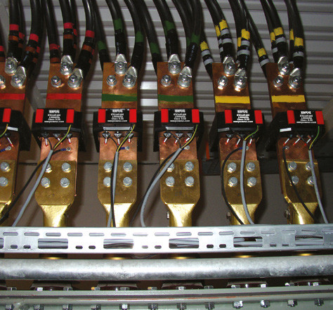
Proper Short-Circuiting: **Specialized shorting plates or shorting cables** must be used to reliably short-circuit the secondary circuit on both sides of the breakpoint, ensuring a continuous current path. Shorting points should be positioned as close as possible to the current transformer itself.
Define Work Boundaries: Personnel are strictly prohibited from performing any work on the circuit segment between the current transformer and the shorting point to prevent accidental contact with energized parts.
Implement safety measures: A supervisor must be present during operation. Personnel must use qualified insulated tools and stand on insulating mats to ensure personal safety.
Note permanent grounding points: When performing tasks such as cleaning terminal blocks, wear necessary protective gear and exercise extreme caution to avoid accidentally disconnecting permanent grounding points installed as protective measures.
Replacing current transformers or their secondary cables is a meticulous task that requires ensuring parameter compatibility between old and new equipment and correct connection.
Requirements for CT Replacement:
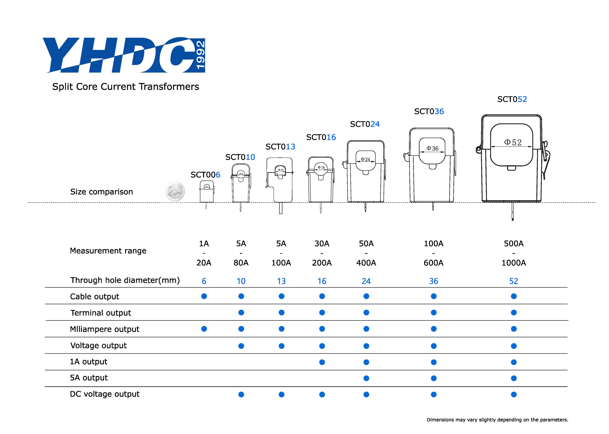
* Model Consistency: The new CT’s transformation ratio, accuracy class, capacity, and other parameters must fully match the original design specifications.
* Correct Polarity: Wiring must follow the original CT’s P1, P2 terminal correspondence with S1, S2 terminals. Reversed connections may cause protection misoperation or metering errors.
* Similar Voltage-Current Characteristics: For protection CTs, their voltage-current characteristics should be similar to other CTs in the same group to ensure protection accuracy.
* Subsequent Calibration: After replacing CTs, all relevant protection settings and measurement instrument multipliers must be rechecked and calibrated to ensure correct system parameter operation.
* Secondary Cable Replacement: When replacing secondary cables, ensure the new cable’s cross-sectional area meets current-carrying capacity and voltage drop requirements. Measure its insulation resistance after replacement to verify compliance.
* Final Polarity Verification: After all replacements are complete and before formal commissioning, the polarity of the entire secondary circuit must be remeasured. This serves as the final safeguard to ensure correct system operation.
Before the new CTs are put into operation or after maintenance, a comprehensive inspection of the appearance and wiring should be conducted before the power is restored.
* Appearance condition: Ensure that the main body of the CT is clean, without dust or oil stains. For oil-filled CTs, check for any oil leakage; for low-voltage split-core CTs, inspect for dust and rust on the cross-section.
* Insulation components: Check the porcelain bushings to ensure there are no cracks, damages, or discharge marks.
* Wiring tightness: Check all the screws of the primary and secondary connection terminals to ensure good contact without rust and prevent loosening due to vibration or thermal expansion and contraction.
* Reliable grounding: Check if the CT housing is reliably grounded. Additionally, the secondary circuits of protective CTs usually require a reliable single-point grounding at a certain point (such as at the terminal block) to prevent induced high voltage. Special attention: The secondary circuits of CTs used for metering are usually not allowed to be grounded to prevent current diversion and affect the accuracy of metering.
Daily inspections and regular maintenance are the key to ensuring the long-term stable operation of current transformers.
*Preventive Test: According to the procedure requirements, a comprehensive preventive test for current transformers should be conducted once every 1-2 years, including measuring insulation resistance, transformation ratio, polarity, and volt-ampere characteristics, etc., to promptly detect potential defects.
*Circuit Integrity: During daily inspections, close attention should be paid to the integrity of the secondary circuit to ensure that there are no signs of disconnection.
*Connection and Condition Check:
Regularly inspect all connection terminals, especially those of outdoor equipment, to check for any signs of looseness or rust.
During the inspection, listen carefully to ensure that there are no abnormal sounds such as discharge inside the CT.
By observing and smelling, confirm that there are no signs of overheating or burnt smell in the equipment.


Copyright © 2024 PowerUC Electronics Co.


