


How to Convert Voltage Signals from 4–20mA Current Loop
The 4–20mA current loop is a commonly used analog signal transmission method in industrial automation. This article explains the basic meaning of the 4–20mA current loop, how current is converted into voltage, and how to select a suitable sampling resistor.
I. Basic Meaning of 4–20mA Current Loop
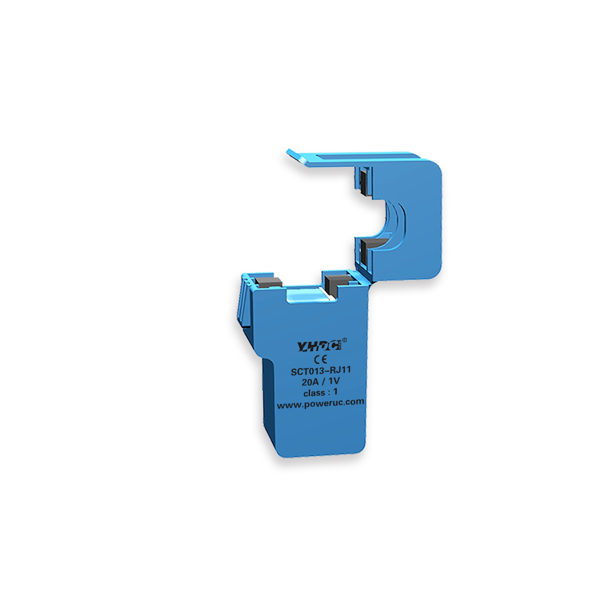
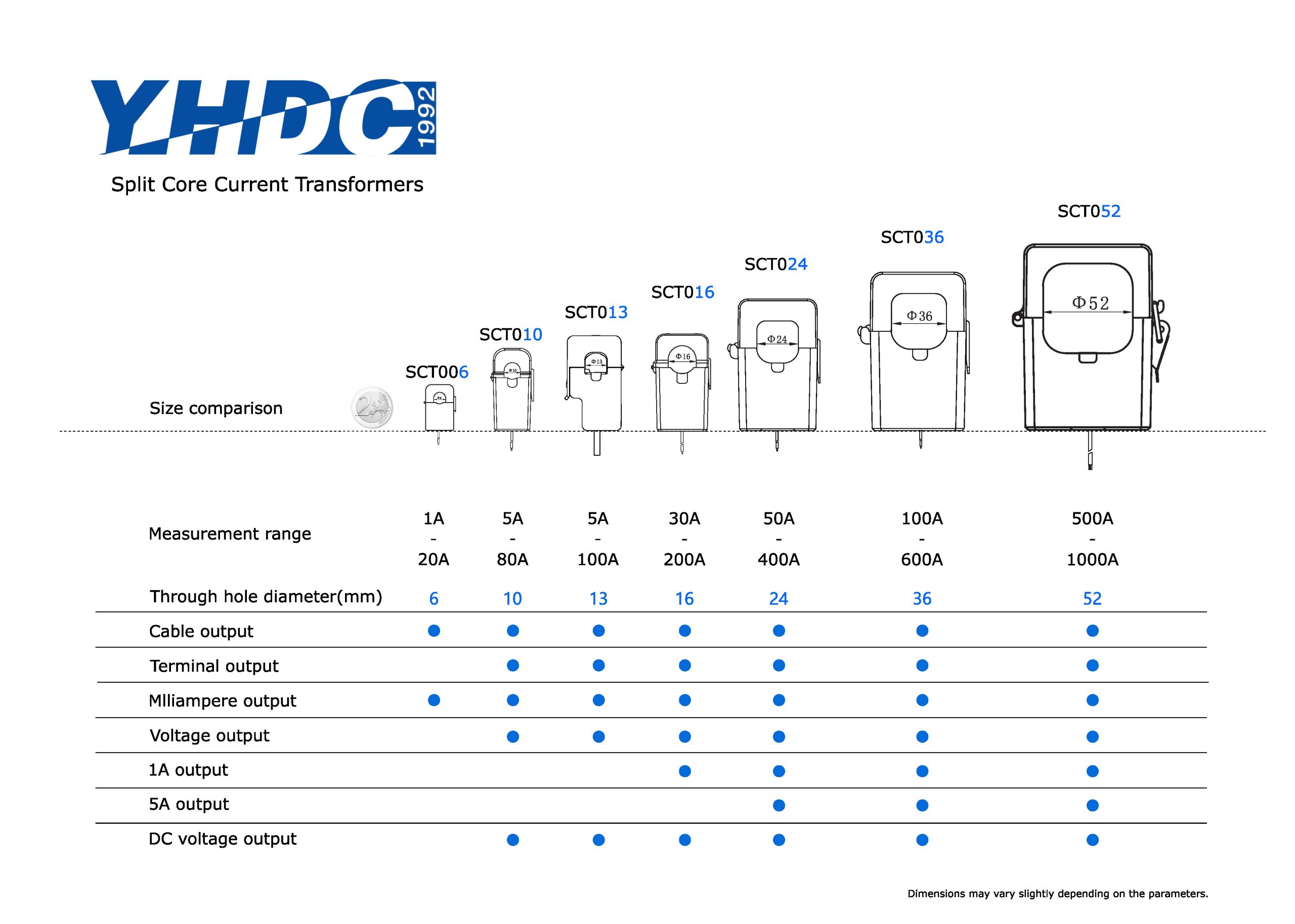
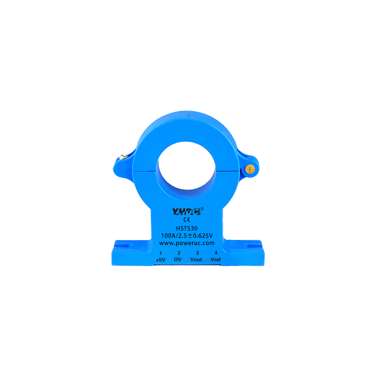
The 4–20mA current loop is a commonly used analog signal transmission method in industrial automation. YHDC produces various current transmitters and voltage transmitters with different shapes and parameters.
In this signal, 4mA represents the minimum range, which is 0%, and 20mA represents the maximum range, which is 100%.
Since the signal starts from 4mA instead of 0mA, the system can still determine whether there is a wire break or fault when the current is lower than 4mA.
II. How Current is Converted to Voltage
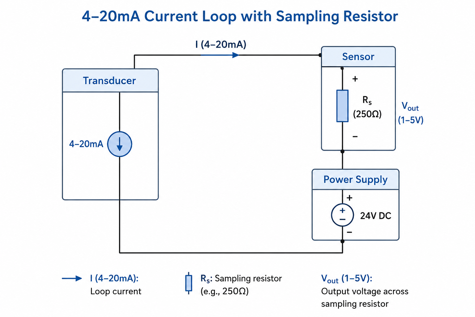
The simplest way to convert a 4–20mA current signal into a voltage signal is to connect a precise resistor in series in the circuit. This resistor is usually called a sampling resistor or load resistor.
According to Ohm’s Law:
Where:
- V represents the voltage across the resistor.
- I represents the current flowing through the resistor.
- R represents the resistance value of the sampling resistor.
When the current flows through the sampling resistor, a corresponding voltage will be generated across the resistor. The greater the current, the higher the voltage.
III. Common Resistance Selection
The accuracy of the sampling resistor directly affects the measurement accuracy. It is recommended to use a precise resistor with 0.1% accuracy.
In practical applications, a 250Ω precision resistor is commonly used to convert a 4–20mA current signal into a 1–5V voltage signal.
| Current | Formula | Output Voltage |
|---|---|---|
| 4mA | V = 0.004A × 250Ω | 1V |
| 20mA | V = 0.02A × 250Ω | 5V |
Therefore, after the 4–20mA current signal passes through a 250Ω resistor, a 1–5V voltage signal can be obtained.
IV. Resistor Power Selection
The power rating of the resistor is also very important. To prevent the increase in temperature inside the resistor from causing changes in the resistance value, it is recommended that the resistor power be at least 10 times the rated power.
The power calculation formula is:
Take a 250Ω resistor as an example. At 20mA:
P = 0.02² × 250 × 10 = 1W
| Sampling Resistor | Output Voltage Range | Recommended Resistor Power |
|---|---|---|
| 100Ω | 0.4–2V | 0.4W |
| 250Ω | 1–5V | 1W |
| 500Ω | 2–10V | 2W |