


How to Connect a Current Switch to a Relay, PLC, NPN, or PNP?
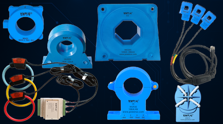
A current switch is widely used in industrial automation, equipment monitoring, and load status detection. It can detect whether current is flowing through a conductor and output a switching signal to a relay, PLC, or control system.
What Is a Current Switch?
A current switch is a sensor that detects the current in a conductor and outputs a switching signal.
It is typically not used to measure precise current values, but rather to determine whether the current exceeds a preset threshold. For example, a 2A fixed-threshold current switch can output a signal when the measured current reaches approximately 2A, confirming that the load has started.
Unlike current transformers and current transmitters, the primary output of a current switch is a digital signal.
Product Type Comparison
| Product Type | Common Output | Main Applications |
|---|---|---|
| Current Switch | NPN, PNP, transistors, MOSFETs, or relay contacts | Determining whether a load is running or stopped |
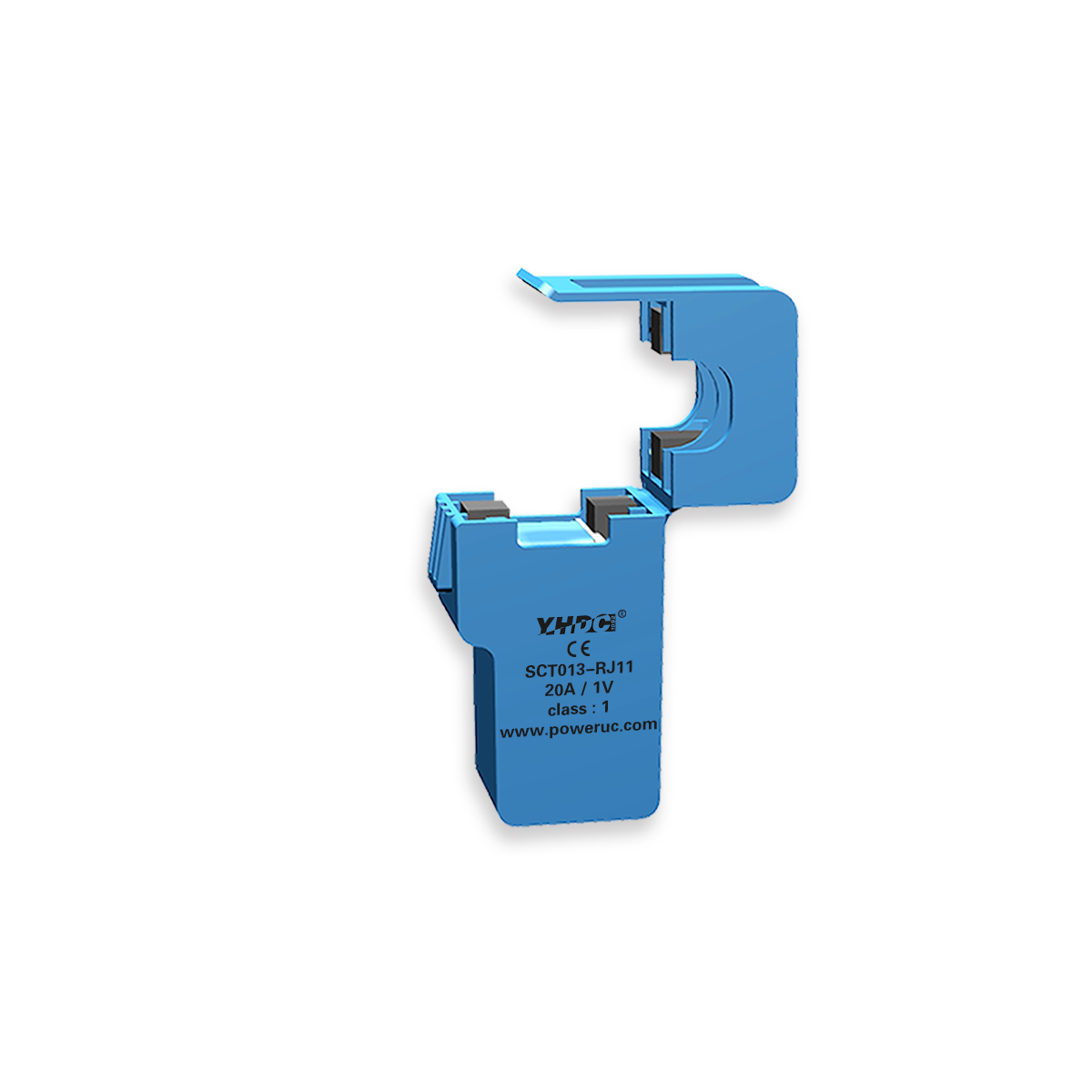
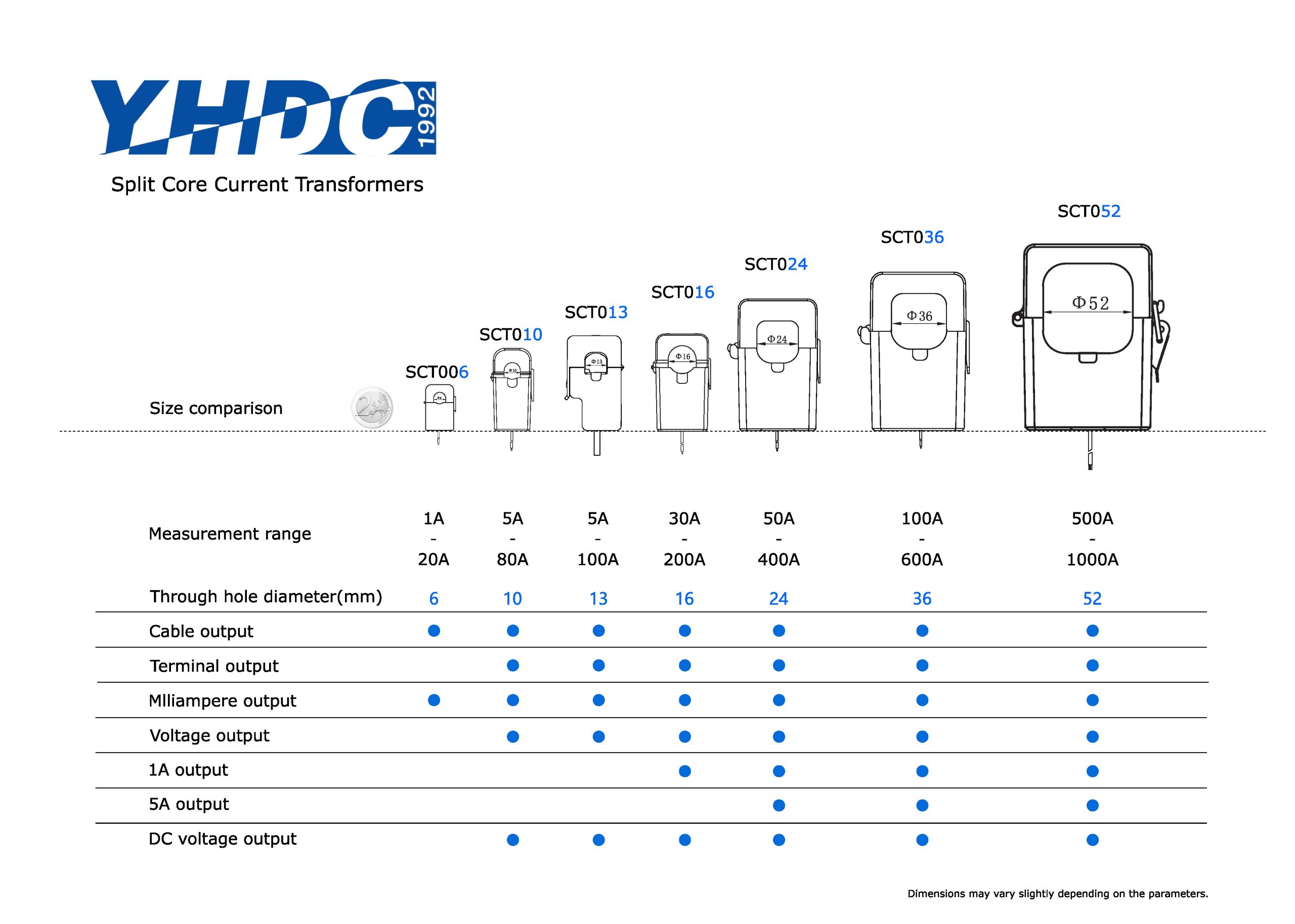
| Current Transformer | 1A, 5A, or milliamp-level AC signals | Current measurement and protection |
| Current Transmitter | 4–20mA, 0–10V | Continuous current measurement |
| Current Monitoring Relay | Relay contacts | Overcurrent, undercurrent, and window monitoring |
Overview of JWY-297 Current Sensing Switch
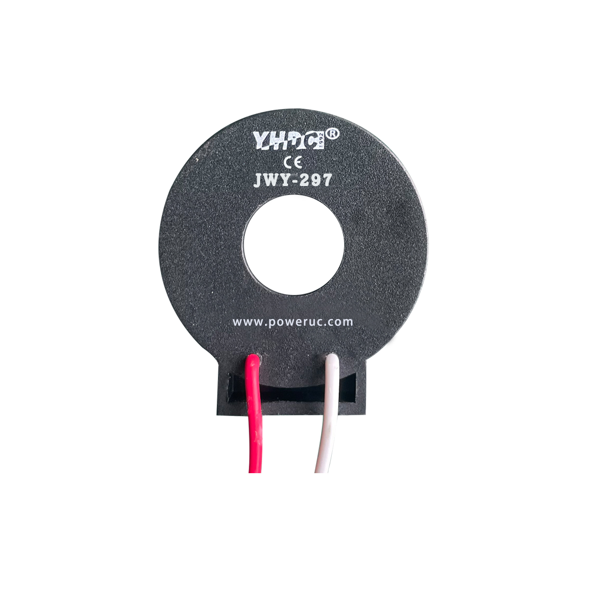
The JWY-297 is an AC current sensing switch that requires no auxiliary power supply and is used to detect whether current is flowing in a conductor.
When the current in the monitored conductor exceeds the trip point, approximately 2A, the internal transistor turns on, enabling digital detection of the “device operational status.”
Its output is an NPN open-collector type, so different wiring methods are required in various control systems.
Key point: An NPN open-collector output does not actively output a positive voltage. It works by pulling the signal line down to 0V when the current is detected.
1. Connecting to a Relay Load
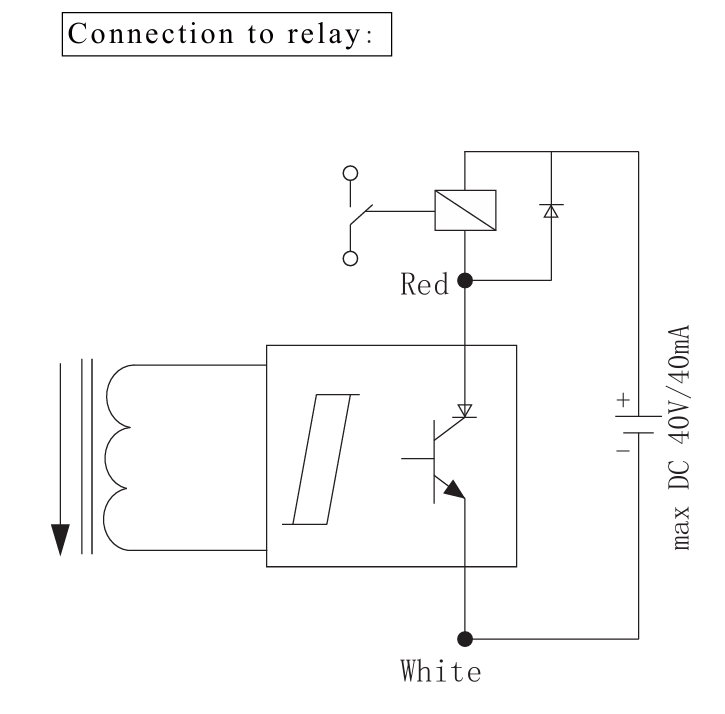
The STWA1S can directly drive small DC relays when the relay coil current is within the output capacity, such as DC 40V / 40mA or less. When current is detected, the output transistor turns on, pulling one end of the relay coil to ground, thereby energizing the relay.
Applicable Scenarios
- Simple equipment operation indication
- Standalone control systems without a PLC
- On/off monitoring of small pumps, fans, and heaters
2. Connecting to a PLC Sourcing Input — Pull-Down Configuration
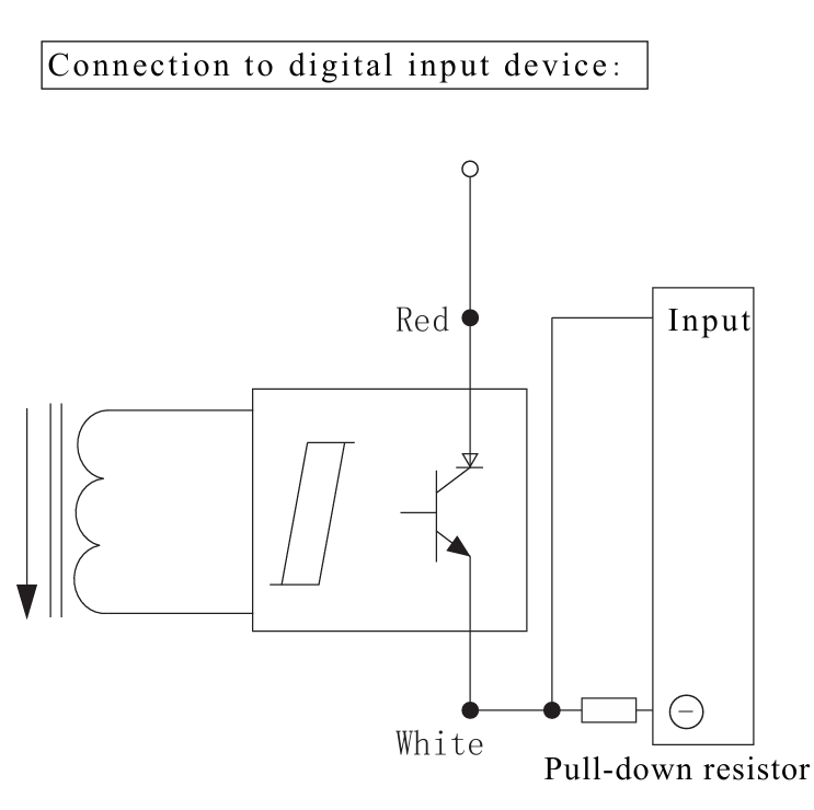
Sourcing input modules provide an internal pull-up voltage, typically +24V. Since the STWA1S output can only pull the signal low, it can directly pull the PLC input to 0V to trigger the signal.
Features
- No external resistors required
- Simplest wiring
- Compatible with most modern PLCs, such as common DI modules from Siemens, Omron, and Mitsubishi
Applications
- Monitoring the operational status of automation systems
- Detecting whether fans, pumps, or heaters are running
- Multi-channel current detection using parallel OR logic
3. Connecting to a PLC Sinking Input — Pull-Up Configuration
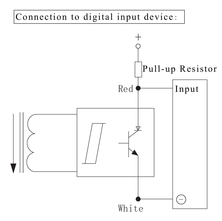
Sinking input modules have an internal pull-down structure and require an external pull-up voltage. In this case, a pull-up resistor must be added to the STWA1S output to ensure the PLC input receives a high level.
Features
- Requires an external pull-up resistor, typically 2.2kΩ–10kΩ
- Suitable for older PLCs or specialized control boards
Applicable Scenarios
- DI inputs on industrial control boards
- Older PLC models, such as some S5 models and early domestic PLCs
4. Connecting to Built-in Digital Modules such as Siemens S5
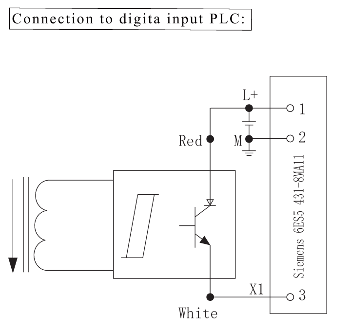
Modules such as the Siemens 6ES5 431 8MA11 already provide an internal pull-up voltage, so the standard STWA1S connection method can be used directly.
- Red wire → Input terminal, for example X1
- Black wire → Common terminal, M
Applicable Scenarios
- Retrofitting of legacy equipment
- Operational status monitoring of S5 systems
- Upgrading existing equipment in server rooms, buildings, and factories
Summary
A current switch provides a simple and reliable way to detect whether a load is running or stopped. Compared with current transformers and current transmitters, it focuses on switching status rather than precise current measurement.
For relay control, it can directly drive small DC relay coils within the rated output capacity. For PLC systems, the wiring method depends on whether the input module is sourcing or sinking. When used with built-in digital modules such as Siemens S5, the current switch can often be connected directly if the module already provides an internal pull-up voltage.
Selection suggestion: Before wiring, confirm the current switch output type, PLC input type, supply voltage, and maximum allowable output current to ensure reliable operation and avoid damage to the control circuit.