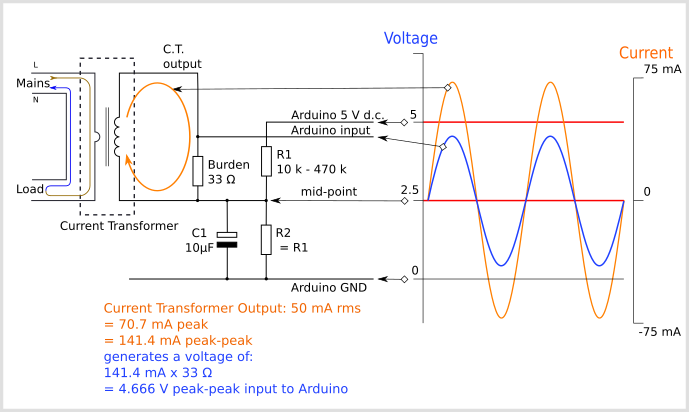
To connect a CT sensor to an Arduino, the output signal from the CT sensor needs to be conditioned so it meets the input requirements of the Arduino analog inputs, i.e. a positive voltage between 0V and the ADC reference voltage.
This give the example of an Arduino board working at 5 V and of the EmonTx working at 3.3 V. Make sure you use the right supply voltage and bias voltage in your calculations that correspond to your setup.
The circuit consists of two main parts, their functions are to change the c.t’s current into a voltage of the correct amplitude, and position this voltage in the centre of the ADC’s input range.
The voltages and currents shown are for a 5 V Arduino, with a 0 – 5 V range for the analogue input, about 1.6 V rms for a sine wave. For the emonTx V2 & V3 and the emonPi, the analogue input range is 0 – 3.3 V, so the midpoint voltage is 1.65 V and the analogue input voltage swings between 0 and 3.3 V (approximately 1 V rms for a sine wave). For the emonTx4 and emonPi2, the analogue input range is 0 – 1 V and is intended for use with 0.333 V rms output current transformers, which do not need a burden. so this resistor is omitted.


Copyright © 2024 PowerUC Electronics Co.