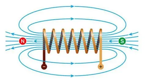
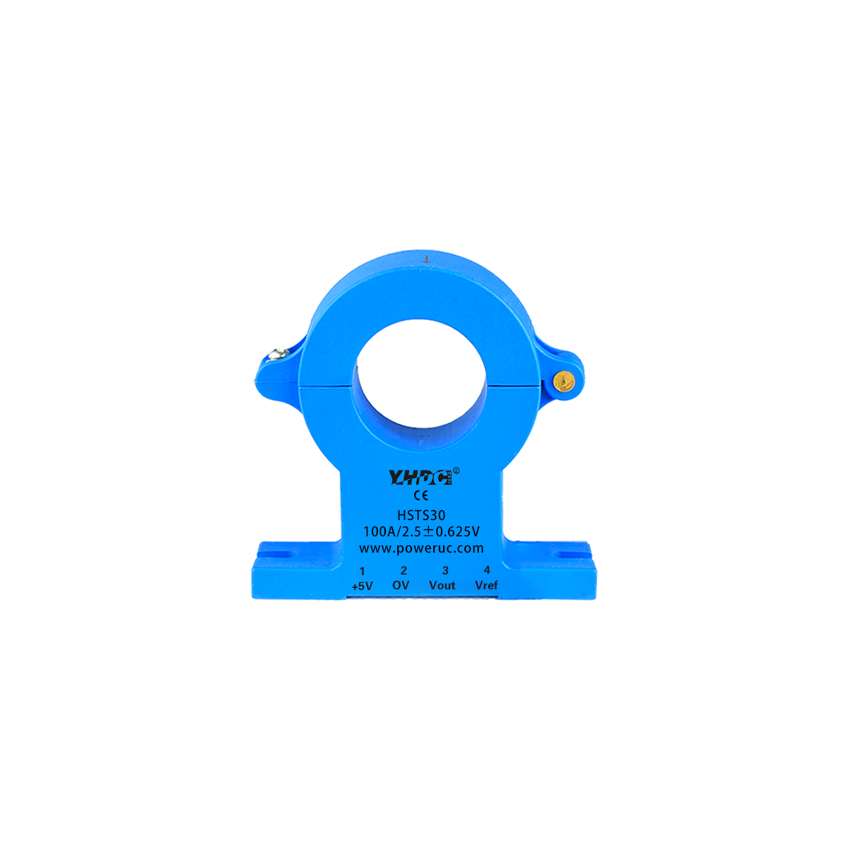
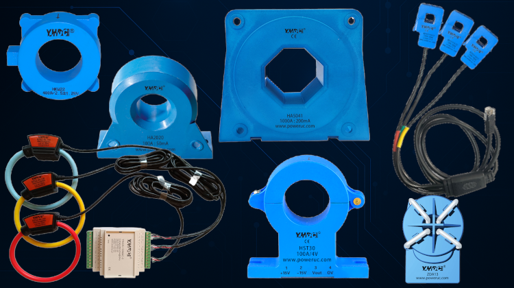
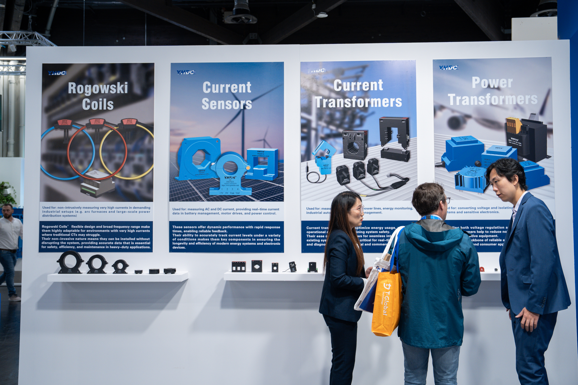
Current transformers (CTs), voltage transformers (VTs, also known as potential transformers (PTs), and power transformers all operate based on the principle of electromagnetic induction, but they differ significantly in their design, purpose, and operating characteristics. Simply put, CTs and VTs are instrument transformers, primarily used to measure and protect current or voltage in power systems, while power transformers are power transformers, primarily used for voltage conversion in power transmission and distribution. Below, I will compare them from multiple perspectives.
The following table summarizes the key differences between the three types of transformers:
| Current Transformer (CT) | Voltage Transformer (VT) | Control/Safety Isolation Transformer | |
|---|---|---|---|
| Applications | Measure and monitor current and protect equipment (such as relays). | Measure and monitor voltage and protect equipment. | Provide electrical isolation and voltage conversion for control circuits and safe power supply (such as preventing electric shock and powering low-voltage equipment). |
| Working Mode | When the primary is connected in series with the load circuit, the secondary must be short-circuited (or connected to a low-impedance load) to avoid dangerous high voltages. | When the primary is connected in parallel, the secondary is open-circuited or connected to a high-impedance load (such as a meter). | The primary and secondary terminals are connected to the power supply and load as required for power transmission and have no measurement function. |
| Transformation ratio characteristics | Current step-down ratio (high current → low current, e.g., 1000A:5A), low secondary voltage. | Voltage step-down ratio (high voltage → low voltage, e.g., 1kV:10V), high secondary impedance. | Voltage step-down ratio (e.g. 220V:24V), with emphasis on isolation and power transfer. |
| Design Features | Fewer primary turns, more secondary turns; high precision, low saturation; small capacity (several VA). | Similar to a small transformer, high precision; small capacity (several VA to tens of VA). | Dual-winding isolation design with shielding for enhanced safety; low-voltage PCB or chassis-mountable; high efficiency, suitable for intermittent or continuous loads; large capacity (several VA to several kilovolts). |
| Load requirements | The secondary must be short-circuited or low-impedance to avoid dangerously high voltages. | The secondary can be left open for high-impedance loads (such as instruments). | When connecting the secondary to an actual load (such as a control device), it can be left open, but this is not recommended. |
| Accuracy and Error | Emphasizes current measurement accuracy (error <1%). | Emphasizes voltage measurement accuracy (error <0.5%). | Emphasis is placed on isolation and efficiency (>65%), not measurement accuracy; voltage regulation is low. |
| Application Scenario | Power metering, protection systems, ammeters. | Voltmeters, power meters, protection relays. | Industrial automation, machine tool controls, medical equipment, security lighting, PCB power modules. |

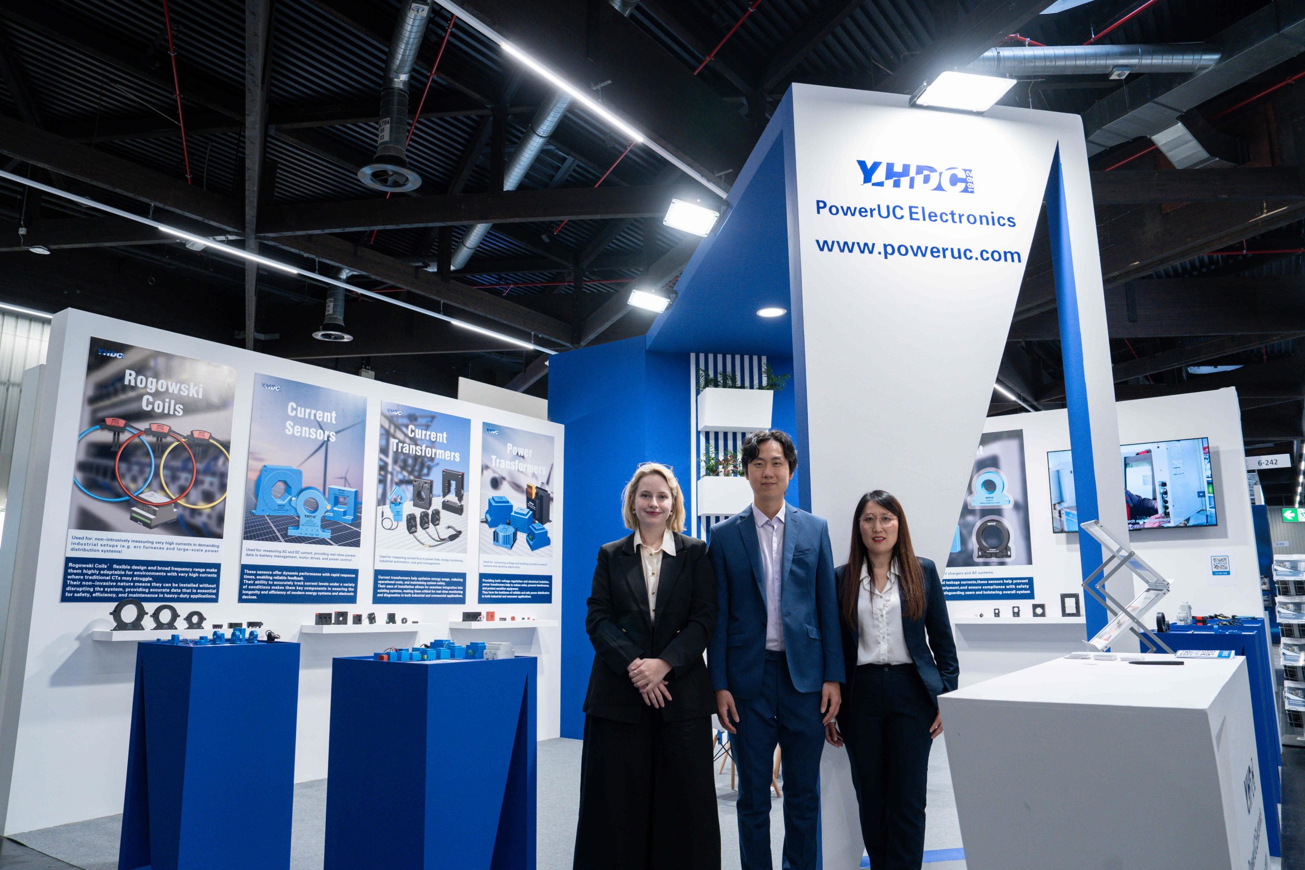

Copyright © 2024 PowerUC Electronics Co.