

In modern electrical and electronic systems, voltage and current sensors play a crucial role. As core components for functions such as power system monitoring, industrial automation, smart home systems, and renewable energy management, these sensors convert voltage or current signals into standardized, measurable, recordable, and controllable signals, providing accurate data support for various applications. This article will delve into the basic principles, main types, performance characteristics, and differences between voltage and current sensors, and analyze their wide-ranging applications in various fields.
A voltage sensor is a device capable of detecting voltage values in a circuit and converting these values into measurable electrical signals. Typically, these signals are current or voltage outputs proportional to the original voltage.
This type of sensor is very important in many places, such as power system monitoring, battery management, industrial process control, and consumer electronics. They ensure that the equipment operates within a safe voltage range and also provide real-time data, facilitating our analysis and control.
The basic principle of a voltage sensor is based on Ohm’s law and electromagnetic induction. The most common types of voltage sensors include:
1. Resistance voltage divider type: This is the simplest and most common type of voltage sensor. It uses two or more resistors connected in series to share the voltage and infers the total voltage by measuring the voltage drop across one of the resistors. This method is suitable for measuring DC and low-frequency AC voltages, but the high-frequency response is limited by parasitic capacitance and inductance.
2. Transformer type (PT/VT) : Voltage transformers (PT) or voltage transmitters (VT) are mainly used in high-voltage AC circuits to proportionally reduce high voltages to a safe and measurable level. They are based on the principle of electromagnetic induction and achieve voltage isolation and conversion through magnetic coupling between the primary coil and the secondary coil. This type of sensor features excellent isolation performance and high precision, and is often used for measurement and protection in power systems.
3. Hall Effect type: Although Hall effect sensors are mainly used for current measurement, some designs can also be used for voltage measurement, especially in situations that require high isolation or the measurement of DC high voltage. It measures indirectly by measuring the magnetic field strength
Voltage, usually requires converting voltage into current or utilizing the magnetic field generated by voltage.
4. Fluxgate type: Fluxgate sensors measure direct current or alternating current by utilizing the saturation characteristics of magnetic core materials in alternating magnetic fields. It features high sensitivity, high precision and good linearity, and is often used for weak current measurement and high-precision applications.
5. Photoelectric isolation type: This type of sensor uses photoelectric conversion technology to achieve electrical isolation between the input and output. The input electrical voltage is converted into an optical signal by the optical transmitter, and the optical signal is then converted into an electrical signal by the optical receiver for output. This method provides extremely high isolation voltage and anti-interference capability, and is suitable for harsh electromagnetic environments.
The PowerUC website offers a variety of principle voltage sensor products, such as Hall effect type, voltage sensor, fluxgate type, and photoelectric isolation type. These products usually have the following characteristics:
Input type: Supports AC (AC) and DC (DC) inputs.
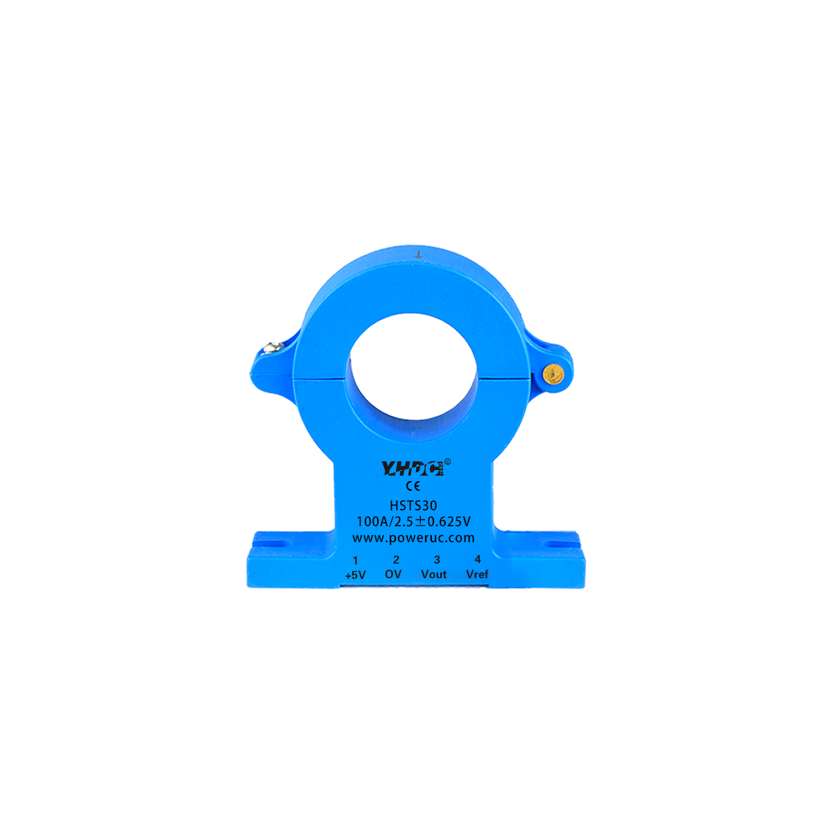
Output type: Instantaneous or true RMS output is provided. The output signal can be electrical voltage (such as ±5V, 2.5±0.625V) or current (such as 25mA, 0-20mA, 4-20mA).
Rated input voltage: Covering a wide range from 50V to 10,000V, it meets the application requirements of different voltage levels. Power supply voltage: Supports multiple power supplies including ±12V, ±15V, 3.3V, 5V, 12V, 24V, etc.
Connection and installation methods: including connection methods such as Screw Terminal, Pins, Cable, etc., as well as installation methods such as Plate, PCB installation, DIN Rail, etc.
It is widely applied in industrial control, power monitoring, new energy power generation and other fields. Its high precision and reliability ensure the stable operation of the system.
A current sensor is a device used to detect the intensity of current in a circuit and convert it into a measurable electrical signal. Similar to voltage sensors, current sensors are also widely used in fields such as power, industrial automation, automotive electronics, and medical equipment. They are crucial for overload protection, energy consumption monitoring, fault diagnosis and system optimization.
The measurement principles of current sensors are diverse, mainly including:
1. Shunt type: A shunt is a low-resistance resistor with an exact known resistance value. When current flows through a shunt, according to Ohm’s Law (V=IR), a voltage drop proportional to the current will be generated across its terminals. By measuring this voltage drop, the current flowing through the shunt can be calculated. The shunt has a simple structure and low cost, but it will introduce certain power consumption and voltage drop, and does not provide electrical isolation.
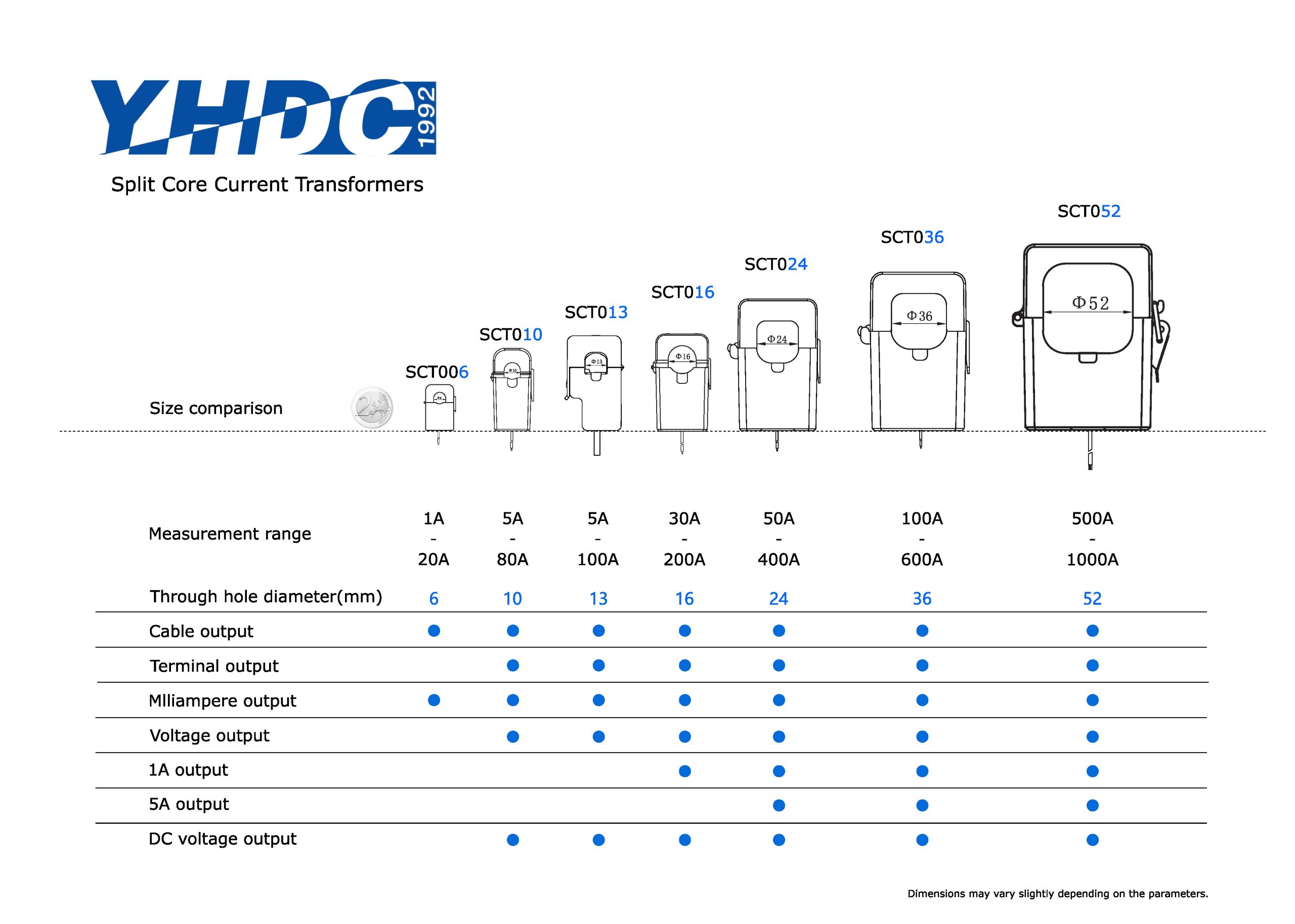
2. Current transformer type (CT) : Current transformers are mainly used to measure large alternating currents. It utilizes the principle of electromagnetic induction to proportionally convert a large current into a small one. The measured current flows through the primary coil of the transformer and induces a proportional current in the secondary coil. Current transformers offer excellent electrical isolation and are widely used in measurement and protection in power systems.
3. Hall Effect type: Hall effect sensors are based on the Hall effect principle. When current flows through a conductor, a magnetic field is generated around it. When a Hall sensor is placed in a magnetic field, it generates a Hall voltage proportional to the strength of the magnetic field. The current can be indirectly measured by measuring the Hall voltage. Hall effect sensors can measure both DC and AC currents and provide electrical isolation, making them suitable for wide current ranges and high-precision measurements.
4. Fluxgate type: Fluxgate sensors measure direct current or alternating current by utilizing the saturation characteristics of magnetic core materials in alternating magnetic fields. It features high sensitivity, high precision and good linearity, and is often used for weak current measurement and high-precision applications.
5. Rogowski Coil type: A Rogowski coil is an air-core coil used for measuring alternating current. It outputs a voltage signal through the change in magnetic flux caused by the induced current, and this voltage is proportional to the rate of change of the current. Roche coils have the advantages of no magnetic saturation, wide frequency response, and high isolation, and are particularly suitable for measuring large currents and high-frequency currents.
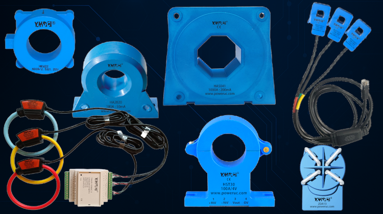
The PowerUC website offers a variety of current sensor products based on different principles, such as Hall effect type, fluxgate type, and Roche coil type current sensors. These products usually have the following characteristics:
Input type: Supports AC (AC) and DC (DC) inputs.
Output type: Instantaneous, true RMS, Digital Signal or TRMS output is provided. The output signal can be voltage (such as ±4V, 2.5±0.625V) or current (such as 50mA, 25mA, 4-20mA).
Rated input current: Covering a wide range from 3A to 5000A, it meets the application requirements of different current levels. Power supply voltage: Supports multiple power supplies such as ±12V, ±15V, 3.3V, and 5V.
Connection and installation methods: Including connection methods such as Cable, Quick plug, Pins, Screw Terminal, as well as installation methods such as Plate, PCB mounting, and Free Hanging.
For instance, PowerUC’s HSTS series current sensors are widely used in industrial control, motor drive, battery management systems and other fields. Their high precision and reliability ensure the stable operation of the system.
Although both voltage sensors and current sensors are used to measure electrical parameters, they differ significantly in terms of the objects they measure, working principles, application scenarios, and performance characteristics.
| Features | Voltage sensor | Current sensor |
|---|---|---|
| Measurement objects | The potential difference (voltage) between two points in a circuit. | The amount of electric charge flowing through a conductor (current). |
| Basic Principles | Voltage divider, electromagnetic induction (current transformer), Hall effect (partial), fluxgate,opto-isolation | Shunt resistor, electromagnetic induction (current transformer), Hall effect, fluxgate sensor, Rogowski coil |
| Connection Method | Typically connected in parallel across the terminals of the circuit being measured | Alternatively, connected in series within the circuit, or using an inductive method (e.g., current transformer, Hall effect) for non-contact measurement |
| Isolation Characteristics | Current transformers, opto-isolators, Hall effect sensors, and fluxgate sensors provide electrical isolation; resistive voltage dividers typically do not. | Current transformers, Hall effect sensors, fluxgate sensors, and Rogowski coils provide electrical isolation; shunt resistors do not. |
| Power Consumption | High internal impedance results in low power consumption, minimizing the impact on the measured circuit. | Shunt resistors have power dissipation and voltage drop; other types of resistors have relatively lower power consumption. |
| Application Scenarios | Power grid voltage monitoring, battery voltage management, power supply output monitoring, equipment over/under voltage protection | Motor current monitoring, load current detection, ground fault protection, energy consumption metering, battery charging and discharging management |
| Key challenges | High-voltage isolation, measurement accuracy, frequency response | Large current measurement, high precision, wide frequency response, and interference immunity |
The measurement purposes are different: voltage sensors focus on potential differences, while current sensors focus on the flow of electric charges. This determines the fundamental differences in their connection methods and measurement principles in the circuit.
The connection methods are different: Voltage sensors are usually connected in parallel in the circuit to measure the potential difference between two points. Current transducers are usually connected in series in circuits to measure the current flowing through conductors or to induce the magnetic field generated by the current through non-contact methods (such as transformers, Hall effect).
Isolation requirements: In high-voltage or strong electromagnetic interference environments, electrical isolation is of vital importance. Both transformer and photoelectric isolation technologies are used to provide isolation in both types of sensors, but current sensors, due to the characteristics of their measurement methods, are usually easier to achieve high isolation.
Power consumption and voltage drop: Shunt type current sensors introduce certain power consumption and voltage drop, which need to be particularly considered in low-power or high-precision applications. Due to its high input impedance, voltage sensors usually have a relatively small impact on the circuit under test.
In practical applications, voltage sensors and current sensors often need to work in coordination to provide comprehensive and accurate monitoring data for power systems or electronic devices. For instance, in electric metering, both voltage and current need to be measured simultaneously to calculate power and energy.
To gain a deeper understanding of voltage and current sensors, it is necessary for us to explore their core working principles in detail. Although it was briefly mentioned in the previous text, this section will provide a more specific description of the mechanism.
A voltage sensor converts voltage signals into measurable electrical signals. Its working principle mainly relies on the following mechanisms:
1 Principle of voltage division by resistance
Mechanism:This is the most intuitive method for voltage measurement. A voltage divider circuit is formed by connecting two or more resistors in series across the two terminals of the voltage to be measured. According to Ohm’s Law, the voltage drop across each resistor is directly proportional to its resistance value. By precisely measuring the voltage across one of the resistors and combining it with the proportional relationship of the resistors, the total electrical voltage can be calculated. For instance, if R1 and R2 are connected in series, the total voltage V = V_R1 + V_R2, and V_R2 = V * (R2 / (R1 + R2)). By measuring V_R2, V can be inferred in reverse.
Features: Simple structure, low cost, suitable for DC and low-frequency AC voltage measurement. However, it does not provide electrical isolation, and in high-frequency environments, the parasitic capacitance and inductance of the resistance can affect the measurement accuracy.
2. Electromagnetic Induction Principle (Voltage Transformer) :
Mechanism: Voltage transformers (PT/VT) utilize the principle of transformers. The high-voltage side (primary coil) is connected in parallel with the high-voltage circuit under test, and the low-voltage side (secondary coil) is connected to the measuring instrument. When high voltage passes through the primary coil, an alternating magnetic field is generated, which induces a proportional low voltage in the secondary coil. By precisely measuring the turns ratio, the measured high voltage can be safely reduced proportionally to the standard measurement range (such as 100V or 110V).
Features: It provides high-voltage isolation, has high measurement accuracy, and is suitable for high-voltage measurement and protection in power systems. It is mainly used for AC voltage measurement.
3. Hall Effect Principle (for some voltage sensors):
Mechanism: Although Hall effect sensors are mainly used for current measurement, voltage measurement can also be achieved by converting voltage to current (for example, through a known resistor), or by indirectly influencing the magnetic field with the electric field generated by the voltage. In this case, the Hall element senses the magnetic field intensity and generates a Hall voltage proportional to the magnetic field intensity. Through calibration, the Hall voltage can be correlated with the original voltage.
Features: It offers electrical isolation and is suitable for both DC and AC voltage measurement, especially having advantages in high-voltage or high-isolation applications.
4. Principle of photoelectric isolation:
Mechanism: The photoelectric isolation voltage sensor achieves electrical isolation through light signals as an intermediate medium. The input voltage signal drives a light-emitting diode (LED) to emit a light signal. After passing through an insulating medium, the light signal is received by a photosensitive receiver (such as a phototransistor) and converted into an electrical signal proportional to the original voltage for output. Since the transmission of optical signals does not involve electrical contact, high-voltage isolation between the input and output is achieved.
Features: It offers extremely high electrical isolation and anti-electromagnetic interference capabilities, with a fast response speed, and is suitable for harsh electromagnetic environments and high-voltage applications.
Current sensors convert current signals into measurable electrical signals. Their working principle mainly relies on the following mechanisms:
1. Principle of the shunt:
Mechanism: The shunt is a precision resistor with a known and very small resistance value. When the current to be measured flows through the shunt, according to Ohm’s Law (V = I * R), a tiny voltage drop proportional to the current will be generated across the shunt. By measuring this voltage drop and combining it with the resistance value of the shunt, the current flowing through the circuit can be calculated.
Features: Simple structure, low cost, suitable for both DC and AC current measurement. However, since it is connected in series in the circuit, it will introduce certain power consumption and voltage drop, and does not provide electrical isolation.
2. Electromagnetic Induction Principle (Current Transformer):
Mechanism: The current transformer (CT) utilizes the principle of a transformer. The measured large current flows through the primary coil (usually the wire passing through the center hole of the transformer), generating magnetic flux in the iron core. This magnetic flux induces a proportional small current in the secondary coil. By precisely measuring the turns ratio, the measured large current can be safely reduced proportionally to the standard measurement range (such as 5A or 1A).
Features: It offers electrical isolation, has high measurement accuracy, and is suitable for large current measurement and protection in power systems. It is mainly used for alternating current measurement.
3. Principle of Hall Effect:
Mechanism: When current flows through a conductor, a magnetic field is generated around it. The Hall effect current sensor places the Hall element in this magnetic field. According to the Hall effect, when current passes through a Hall element and is in a magnetic field perpendicular to the current direction, a magnetic field intensity and current intensity will be generated between the two sides of the Hall element
Hall voltages that are all proportional. By measuring this Hall voltage, the magnitude of the current being measured can be calculated. Closed-loop Hall sensors also counteract magnetic fields through feedback current, further enhancing accuracy and linearity.
Features: It can measure both DC and AC currents, provides electrical isolation, has a fast response speed, and is suitable for wide current ranges and high-precision measurements.
4. Fluxgate Principle:
Mechanism: Fluxgate sensors utilize the nonlinear magnetization characteristics of magnetic core materials in an alternating magnetic field. It usually contains a magnetic core that is easily saturated and an excitation coil. When the magnetic field generated by the measured direct current is superimposed on the alternating magnetic field produced by the excitation coil, it will change the saturation point of the magnetic core, thereby affecting the induced voltage waveform of the excitation coil. By detecting the changes in this waveform, direct current can be precisely measured.
Features: High sensitivity, capable of measuring weak direct current, with excellent stability and linearity.
Mechanism: A Rogowski coil is a hollow coil uniformly wound around a non-magnetic skeleton. It generates an induced voltage across the coil by inducing an alternating magnetic field produced by the alternating current being measured. According to Faraday’s law of electromagnetic induction, this induced voltage is directly proportional to the rate of change (dI/dt) of the measured current. In order to obtain the current signal, the induced voltage needs to be integrated.
Features: No magnetic saturation issue, wide frequency response, high isolation, suitable for measuring large currents, high-frequency currents and transient currents.
Voltage sensors and current sensors have extensive applications in modern industry and daily life. They are key components for the normal operation and optimization of many systems.
1. Power System Monitoring and Protection:
Grid voltage monitoring: Real-time monitoring of the voltage level in the transmission and distribution grid to ensure stable operation of the grid and prevent damage to equipment caused by overvoltage or undervoltage.
Generator and transformer protection: Monitor the voltage output of generators and transformers. Once abnormal voltage fluctuations occur, immediately trigger the protection mechanism to prevent equipment damage.
Reactive power compensation: In power systems, voltage sensors are used to detect voltage deviations and guide reactive power compensation devices to make adjustments to improve the power factor of the power grid.
2. Renewable Energy Applications:
Solar inverter: Monitor the output voltage of the solar panel and the input/output voltage of the inverter to ensure the maximum power point tracking (MPPT) efficiency and power quality.
Wind power generation: Monitor the output voltage of wind turbine generators to ensure the stability of grid-connected voltage.
Energy storage system: In battery energy storage systems, voltage sensors are used to monitor the voltage of the battery pack, assess the state of charge (SOC) and state of health (SOH), and prevent overcharging and overdischarging.
3. Industrial Automation and Control:
Power management: Monitor the voltage stability of the power supply for industrial equipment to ensure that the equipment operates at the rated voltage.
Motor control: In frequency converters and servo systems, voltage sensors are used to detect the DC bus voltage and the motor phase voltage to achieve precise control.
Process control: In industries such as chemical engineering and metallurgy, voltage sensors are used to monitor the electrical voltage parameters of key equipment during the production process to ensure process stability.
4. Electric Vehicles and Charging Stations:
Battery Management System (BMS) : Precisely monitors the voltage of each battery cell in the power battery pack of electric vehicles to prevent overcharging, overdischarging and imbalance, and extend battery life.
Charging piles: Monitor the voltage during the charging process to ensure charging safety and efficiency.
5. Consumer Electronics:
Power adapter: Monitors the output voltage to ensure a stable power supply for the device.
Household appliances: Some high-end home appliances integrate voltage monitoring functions to protect the internal circuits.
1. Power System Monitoring and Protection:
Power grid current monitoring: Real-time monitoring of the current load in the transmission and distribution network to prevent overload and optimize power dispatching.
Short-circuit and overload protection: Detect abnormally large currents in the circuit, trigger circuit breakers or fuses to act, and protect equipment and lines.
Fault diagnosis: By analyzing the current waveform and magnitude, diagnose problems such as ground faults and interphase short circuits in the power system.
2. Renewable Energy Applications:
Solar inverter: Monitor the input/output current of the inverter, evaluate the power generation efficiency and power quality.
Wind power generation: Monitor the output current of the wind turbine generator to ensure the stability of the grid-connected current.
Energy storage system: Monitor the charging and discharging current of the battery pack, conduct precise state of charge (SOC) management and battery health assessment.
3. Industrial Automation and Control:
Motor drive and control: Precisely measure motor current, implement advanced control strategies such as vector control and torque control, and enhance motor efficiency and performance.
Load monitoring: Monitor the current consumption of equipment on the production line, determine the operating status of the equipment, and conduct predictive maintenance.
Welding equipment: Precisely control the welding current to ensure welding quality.
4. Electric Vehicles and Charging Stations:
Battery Management System (BMS) : Precisely monitors the charging and discharging current of the power battery pack in electric vehicles, prevents overcurrent, and ensures battery safety.
Charging piles: Monitor charging current to achieve constant current charging and precise control of the charging process.
5. Smart Home and Building Applications:
Energy consumption monitoring: Monitor the real-time electricity current of a household or building to help users understand energy consumption and achieve energy-saving management.
Leakage protection: By detecting leakage current, it promptly cuts off the power supply to prevent electric shock accidents.
6. Medical Devices:
Medical power supply: Monitor the power current of medical equipment to ensure stable operation of the equipment and patient safety.
Diagnostic equipment: In some diagnostic devices, current sensors are used to measure weak biological current signals.


Copyright © 2024 PowerUC Electronics Co.


