


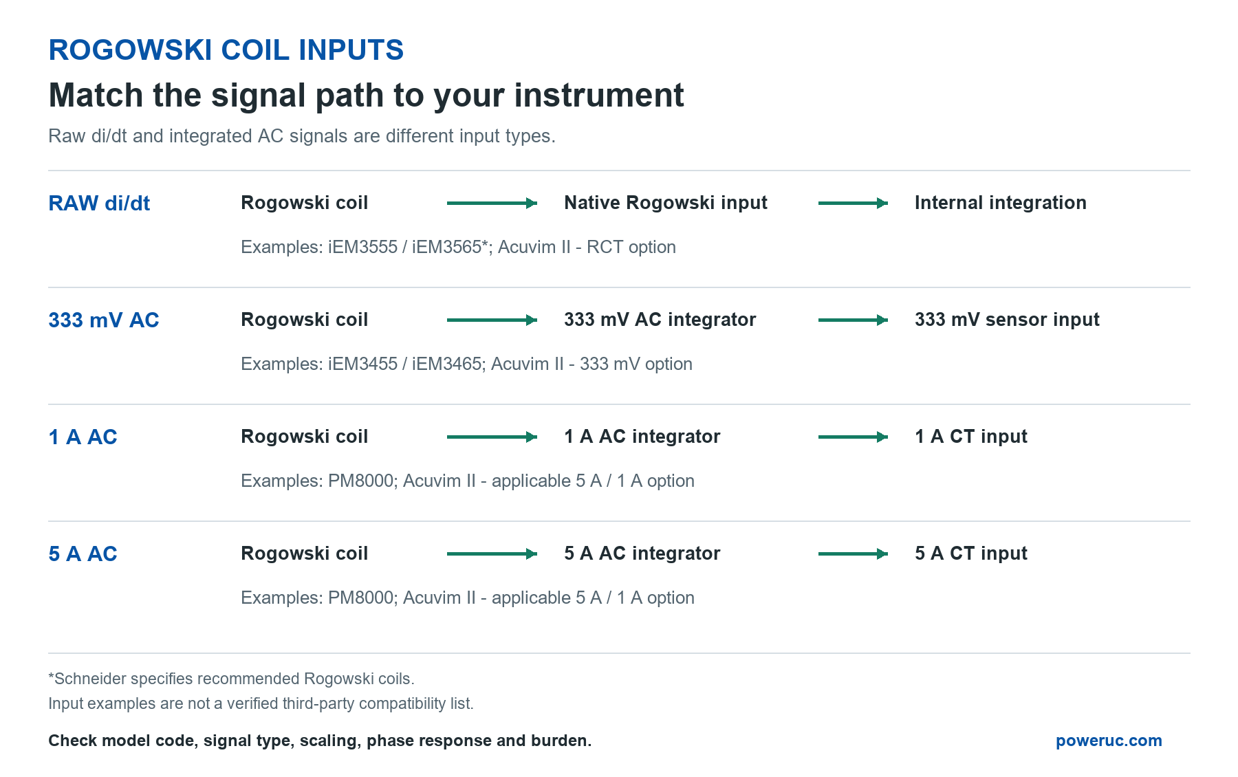
Choosing a Rogowski coil starts with one question: what signal does the receiving instrument actually accept? A meter designed for a raw Rogowski coil, a 333 mV sensor or a conventional 1 A or 5 A current transformer requires a different signal path.
This guide explains the four input types, identifies examples of equipment that supports them, and shows how to check your own instrument before selecting a coil and integrator.
The Four Input Types at a Glance
| Input Type | Signal Expected | Equipment Examples | Rogowski Signal Path |
|---|---|---|---|
| Raw Rogowski / di/dt | Unintegrated coil voltage; the instrument performs integration. | Schneider iEM3555 / iEM3565; Acuvim II with RCT input option. | Matched coil connected to a native Rogowski input; confirm sensitivity and recommended sensors. |
| 333 mV AC | AC voltage waveform proportional to primary current. | Schneider iEM3455 / iEM3465; Acuvim II with 333 mV input option. | Matched Rogowski coil plus a suitable 333 mV AC integrator; not a bare coil. |
| 1 A AC | AC current signal with a nominal 1 A secondary rating. | PowerLogic PM8000; Acuvim II with the appropriate 5 A / 1 A input configuration. | Matched Rogowski coil plus an integrator with a suitable 1 A AC output stage. |
| 5 A AC | AC current signal with a nominal 5 A secondary rating. | PowerLogic PM8000; Acuvim II with the appropriate 5 A / 1 A input configuration. | Matched Rogowski coil plus a suitably rated 5 A AC integrator, not a voltage-output integrator. |
These are input-category examples, not a list of approved PowerUC-to-meter combinations. Schneider’s installation sheet, PowerLogic catalog and Accuenergy’s Acuvim II configuration page document these distinctions. Acuvim II is offered with different input options; do not assume a purchased unit accepts all of them.
1. Which Devices Accept Raw Rogowski di/dt Output?
A bare Rogowski coil produces a voltage proportional to the rate of change of current: v(t) = M x di(t)/dt. Integration is needed to recover a signal proportional to the current waveform. This function can be inside the receiving instrument or in an external integrator.
Suitable equipment includes meters with a dedicated Rogowski input, compatible power-quality analyzers, and measurement systems with correctly configured analog or digital integration. A generic voltage input or oscilloscope channel can capture the raw voltage, but does not automatically convert it into an accurate current measurement.
Schneider iEM3555/iEM3565 are Rogowski-input examples; their documentation specifies Schneider-recommended coils. Acuvim II offers an RCT input option. Neither fact establishes compatibility with an arbitrary third-party coil. Confirm sensitivity, supported sensor types, wiring and calibration with the instrument supplier.
The sensitivity specification matters. For example, PowerUC RFSY lists 50 mV/kA at 50 Hz and 60 mV/kA at 60 Hz. This is a raw, frequency-dependent signal, not an integrated 333 mV AC output. Two sensors described in millivolts may therefore require completely different inputs.
Signal path: Rogowski coil -> matched native Rogowski input -> internal integration and current calculation.
Do not add an external integrator to a raw-coil input unless the instrument supports an appropriate linear-input mode. Integrating an already integrated signal can produce incorrect amplitude and phase.
2. Which Devices Accept 333 mV AC?
A 333 mV input usually refers to a low-voltage current-sensor channel receiving 0.333 V RMS at the sensor’s rated primary current. Its waveform represents current, rather than di/dt. Confirm the manufacturer’s definition of the nominal level.
Schneider iEM3455/iEM3465 support 0.333 V or 1 V nominal LVCT inputs. Acuvim II is available with a 333 mV input option. Check the ordered hardware configuration and the selected range before connecting a sensor.
For a Rogowski installation, an external integrator converts the raw coil output into the required AC voltage. The PowerUC TRV01 offers voltage-output variants including 0.333 V; select the matching coil, primary-current rating and output configuration. This describes a potential signal interface, not a manufacturer-approved pairing with the example meters.
Signal path: Rogowski coil -> matched 333 mV AC integrator -> 333 mV current-sensor input.
For an illustrative 600 A / 333 mV system, 600 A RMS corresponds to 333 mV RMS and 300 A corresponds to 166.5 mV RMS. For a sine wave, 333 mV RMS is about 471 mV peak. A data-acquisition input must accommodate the waveform’s positive and negative peaks, not just its RMS value.
A 333 mV AC signal is not interchangeable with 333 mV DC. Nor does an instrument’s mains-voltage measurement input establish support for a 333 mV current sensor.
3. Which Devices Accept 1 A AC?
Many CT-operated energy meters and power meters accept a nominal 1 A secondary current. PowerLogic PM8000 specifications include this rating; Acuvim II also offers a 5 A/1 A input option. The exact installed configuration and setup remain decisive.
A bare Rogowski coil cannot supply this current. Use an integrator with a current-output stage, such as the appropriate PowerUC TRA05 configuration, after checking its output rating and load capability against the instrument requirements.
Signal path: Rogowski coil -> matched 1 A AC integrator -> 1 A CT input.
As an illustrative scaling example, a 600 A / 1 A system produces 0.5 A at 300 A primary current. Configure the meter for the actual system ratio, not a ratio copied from a previous installation.
4. Which Devices Accept 5 A AC?
Nominal 5 A inputs are common on CT-operated power meters. PM8000 specifications also include this rating, and the Acuvim II 5 A/1 A option provides another example. The PM8000 FAQ separately confirms that PM8000 does not accept a native Rogowski-coil input.
A Rogowski system needs a suitably rated current-output integrator. The PowerUC TRA06 provides a 5 A AC output option. Check the complete combination, including power supply, burden, frequency response and accuracy; an output label alone does not establish compatibility.
Signal path: Rogowski coil -> matched 5 A AC integrator -> 5 A CT input.
For an illustrative 600 A / 5 A system, 300 A primary current corresponds to 2.5 A output. A 1 A system and a 5 A system are not interchangeable simply because both use CT terminals.
Load capability is particularly important for current outputs. For a resistive load, burden in VA = secondary current squared x total loop resistance. At 0.2 ohm, the burden is 0.2 VA at 1 A but 5 VA at 5 A. These are calculation examples, not TRA05 or TRA06 output-capability ratings. Include both the instrument and the complete cable loop when checking the integrator’s permitted load.
How to Check Your Own Equipment
- Record the complete model and input option. Read the nameplate, full order code, installed input module and hardware revision. A family brochure may describe several mutually exclusive input versions.
- Find the current-measurement specification. Search the manual for “Rogowski,” “RCT,” “di/dt,” “LVCT,” “333 mV,” “0.333 V,” “1 A,” “5 A,” “burden” and “input impedance.” Check the current-sensor channel, not the auxiliary supply or voltage-measurement channel.
- Identify who performs integration. An explicit raw-Rogowski input needs the specified coil sensitivity and integration settings. A linear 333 mV, 1 A or 5 A input needs a proportional AC signal from the appropriate external integrator. A selectable sensor mode must be set correctly.
- Check the electrical limits. For raw coils, check sensitivity at the stated reference frequency, input range and supported sensor requirements. For 333 mV, check RMS versus peak ratings, input impedance and waveform headroom. For 1 A/5 A, check nominal current, measurement range and burden against the integrator’s drive capability.
- Check measurement performance. Confirm operating frequency, bandwidth, phase error, polarity and phase assignment. Accurate current magnitude alone does not guarantee accurate active power or energy. Current and voltage waveforms must remain correctly aligned. A slow DC or 4-20 mA RMS transmitter is not a substitute for a waveform input used for power calculation.
- Verify wiring and configuration. Use the instrument’s actual wiring diagram and connector pinout. Labels such as I+, I-, S1 and S2 do not identify the signal type by themselves. Confirm shielding, grounding, channel mapping, primary-current scaling and any required integrator supply.
- Ask for written confirmation when specifications are incomplete. Send the supplier the full instrument code and proposed sensor/integrator datasheets. Ask whether the input accepts raw di/dt or an integrated waveform, what nominal level it requires, what load it presents, and whether the proposed combination is supported. If the manual is silent, compatibility is unconfirmed.
Never connect a 1 A or 5 A output to a 333 mV input. Changing the CT ratio in software cannot change the physical input circuit.
Choosing a PowerUC Rogowski Solution
For a confirmed native Rogowski input, evaluate a raw coil such as RFSY against the instrument’s sensitivity and sensor requirements. For a 333 mV input, evaluate a matched coil with the appropriate TRV01 configuration. For 1 A and 5 A inputs, evaluate the relevant TRA05 and TRA06 configurations respectively.
These are starting points for engineering selection, not universal compatibility claims. Share your instrument’s full model code, input specification, primary-current range, operating frequency and cable length with PowerUC. The correct solution is the one that matches the complete measurement chain: coil, integration, output, wiring and instrument settings.