
In modern energy metering systems, accurate current measurement is crucial. The Atmel M90E32AS is a high-performance, wide-dynamic-range multiphase energy metering IC widely used in various energy meters and power monitoring equipment. Current transformers (CTs) play an indispensable role in safely and accurately transmitting high-voltage, high-current signals to the M90E32AS for processing. This article will delve into the operating principles of current transformers and how to properly connect them to the M90E32AS for reliable current measurement.
The Atmel M90E32AS is a high-performance integrated circuit designed for multiphase energy metering. It integrates six independent second-order Sigma-Delta ADCs capable of simultaneously processing three-phase voltage and current signals. The chip’s internal digital signal processor (DSP) performs complex calculations on the data collected by the ADCs to derive key energy parameters such as active power, reactive power, apparent power, power factor, frequency, and RMS values of voltage and current. The M90E32AS supports current sampling through a current transformer (CT) or a Rogowski coil, and voltage sampling through a resistor divider network.
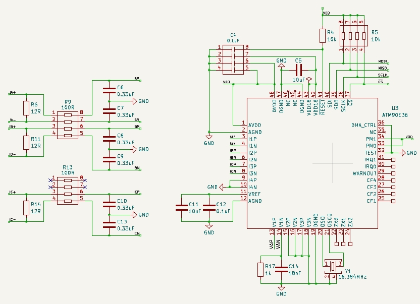
The M90E32AS chip provides three sets of differential current input pins: I1P/I1N, I2P/I2N, and I3P/I3N, corresponding to the measurement of three-phase current. These pins are the input terminals of the analog ADC channels, allowing flexible channel mapping to adapt to different three-phase system configurations (such as three-phase four-wire or three-phase three-wire).
The ADC inside the chip is responsible for converting the analog current signal into a digital signal. The M90E32AS has a high dynamic range and high accuracy, which can ensure accurate measurement over a wide current range. The data sheet states that current sampling is performed through a current transformer (CT) or a Rogowski coil (di/dt coil) [1]. This means that the external sensor converts the current signal into a voltage signal acceptable to the M90E32AS.
The M90E32AS’s DSP not only calculates energy parameters but also supports gain and phase angle compensation to correct for errors introduced by external sensors and circuits. This is crucial for ensuring the accuracy of the entire metering system. The chip also features programmable startup and no-load power thresholds, as well as current and voltage transient signal monitoring. These features enable the M90E32AS to operate stably and reliably in complex power environments.
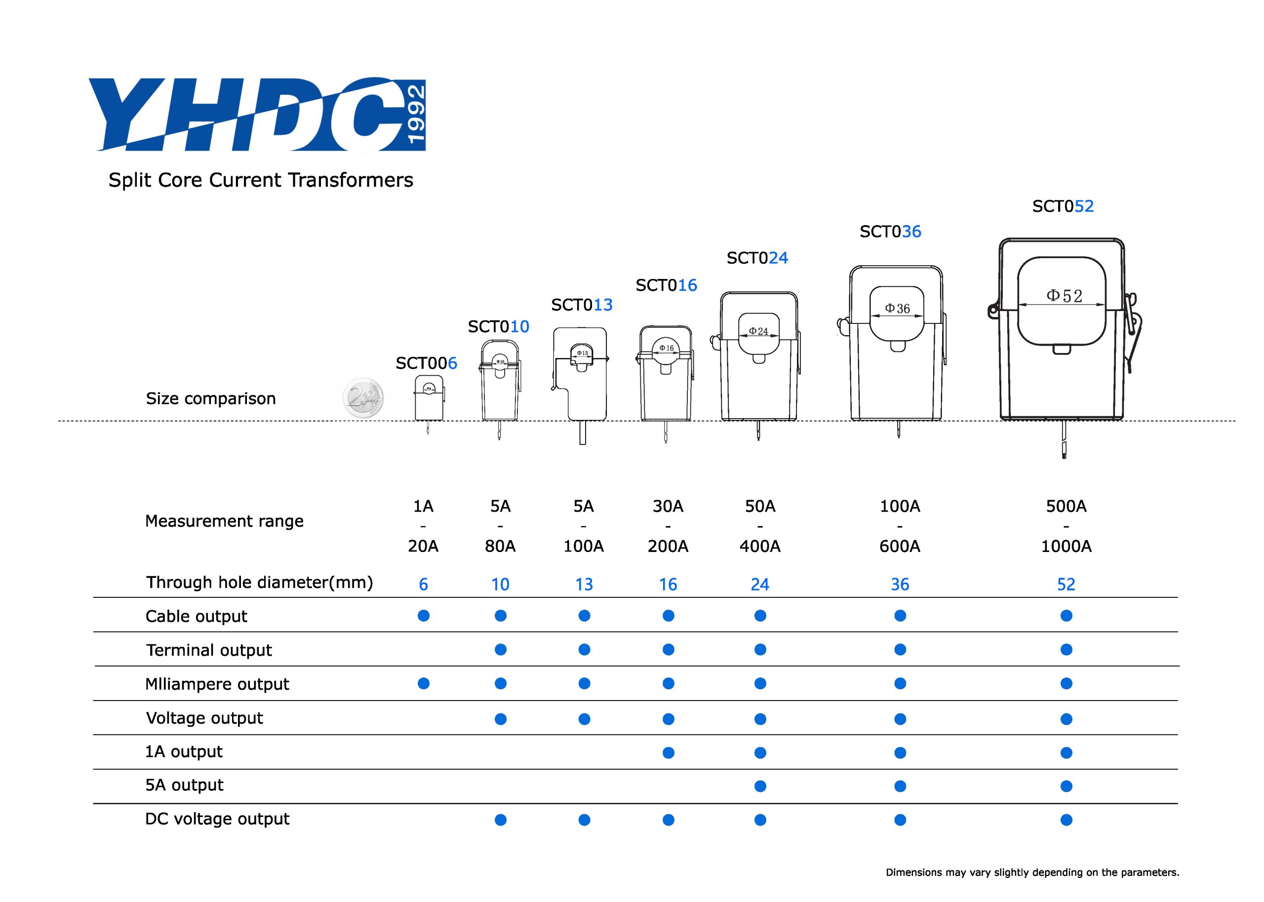
A current transformer (CT) is a special type of transformer used to proportionally convert large currents into smaller ones for measurement, protection, and control. Its primary functions are current isolation and current scaling. The operating principle of a CT is based on the law of electromagnetic induction: when current flows through the primary winding (usually the wire running through the center of the CT), it generates magnetic flux in the core. This flux induces an electromotive force in the secondary winding, generating a secondary current.
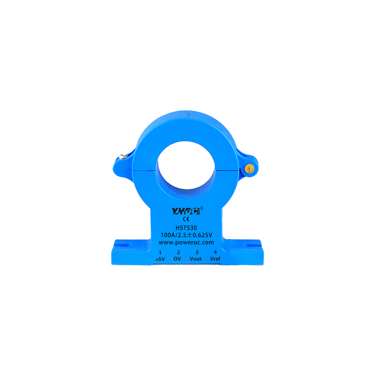
A CT’s ratio is the ratio of its primary-side rated current to its secondary-side rated current, for example, 100A/5A or 100A/0.1A. This means that when 100A flows through the primary, the secondary output will be 5A or 0.1A. In energy metering applications, CTs with a secondary output of milliamperes or less are typically selected to allow direct connection to the current input of a metering chip.
A CT’s accuracy class indicates its measurement error within its rated current range. For example, a 0.2S-class CT indicates an error within a specific current range of ±0.2%, which is critical for high-precision energy metering.
A CT’s burden refers to the impedance of the measuring instrument or device connected to its secondary side. The secondary side of a CT must always be closed; otherwise, an open circuit will cause high voltage to develop on the secondary side, potentially damaging the CT or posing a danger to personnel. Isolation: CTs provide electrical isolation between the primary-side high-voltage circuit and the secondary-side low-voltage measurement circuit, thereby improving system safety and reliability.
In energy metering, CTs are often used to measure high currents in the main circuit. CTs can reduce the voltage and current of the high-current signal in the main circuit, converting it into a low-current or low-voltage signal that the metering chip can process. This not only protects the metering chip from direct impact from high voltage and current, but also makes metering system design more flexible and secure.
Connecting current transformers to the Atmel M90E32AS chip requires careful consideration of the signal conditioning circuit to ensure measurement accuracy and chip safety. The M90E32AS chip’s current input pins (I1P/I1N, I2P/I2N, and I3P/I3N) are differential inputs, meaning they measure the voltage difference between the two pins. Therefore, the current transformer output typically needs to be converted to a voltage signal through a sampling resistor before being fed into the chip’s differential inputs.
We can see how a current transformer (CT) is connected. Typically, the secondary side of the CT is connected to a small-value shunt resistor. When current flows through the shunt resistor, a voltage drop proportional to the current is generated across it. This voltage drop serves as the input signal for the M90E32AS chip’s ADC.
Using single-phase current measurement as an example, the CT’s secondary output is connected to the shunt resistor, which is then connected to the I_P and I_N pins of the M90E32AS chip. To improve measurement accuracy and suppress common-mode noise, a capacitor is typically connected in parallel across the shunt resistor to form an RC filtering network. Furthermore, a voltage divider network or bias circuit may be required to provide an appropriate bias voltage to ensure the ADC input is within the operating range of the M90E32AS.


Copyright © 2024 PowerUC Electronics Co.


