


Current Transformer Phase Angle Error: The Invisible Factor Behind Energy Monitoring Accuracy
In power systems, precise energy metering is the cornerstone for fair transactions, energy conservation, and stable system operation.
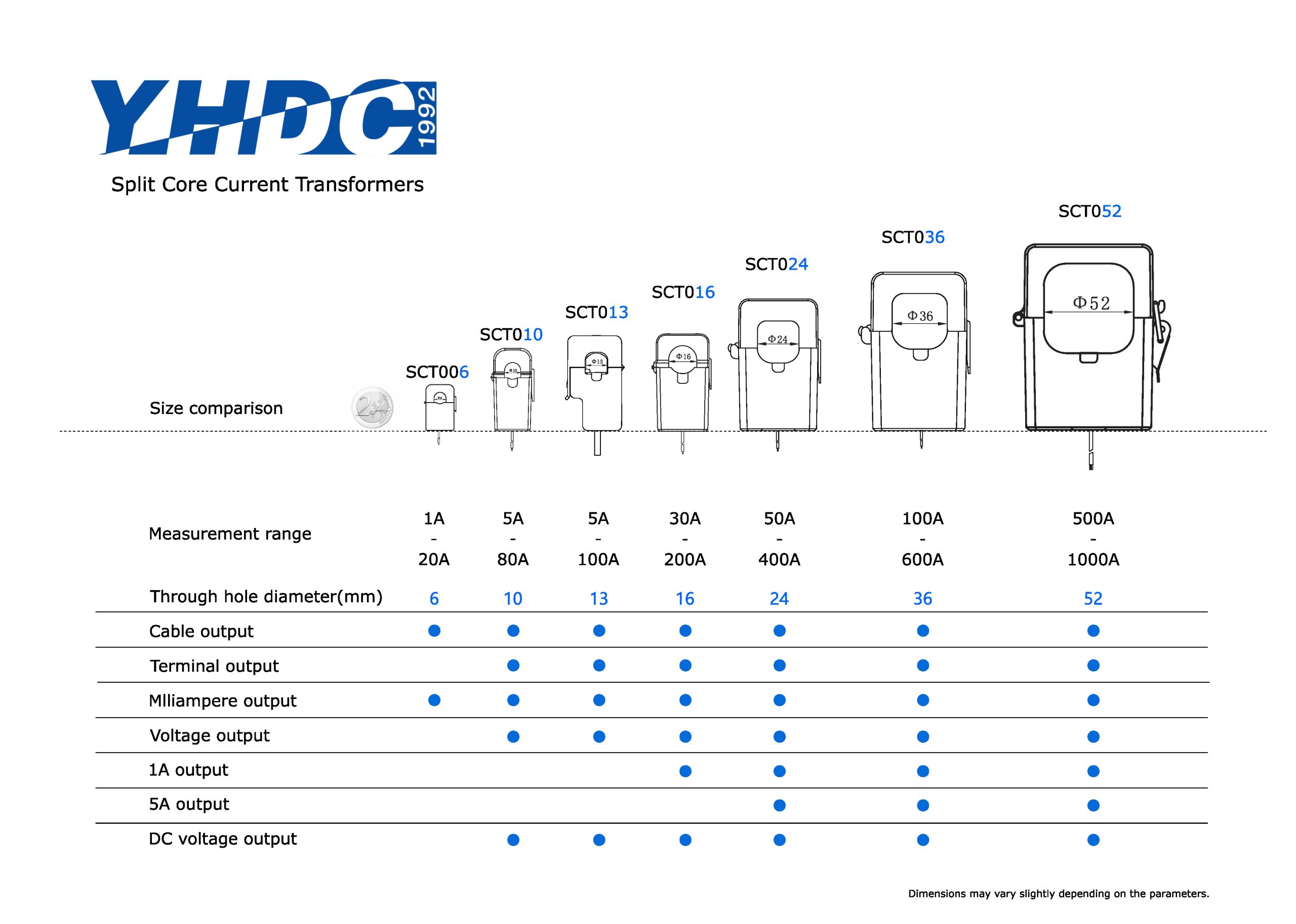
As a critical component in energy monitoring systems, the accuracy of current transformers (CTs) directly determines the precision of final readings.
However, beyond the well-known “ratio error” (amplitude error), a frequently overlooked yet crucial parameter—phase angle error—can have a critical impact on energy measurement accuracy under specific conditions.
1. What is Current Transformer Phase Angle Error?
To understand phase angle error, we must first recognize the gap between ideal theory and practical reality.
- Ideal scenario: An ideal current transformer should output a secondary current signal that is exactly opposite in phase to the primary (main circuit) current signal, maintaining a perfect 180° phase difference.
- Reality: In actual transformers, the secondary current phase does not precisely oppose the primary current by 180°, but instead exhibits a slight angular deviation. The angle between this actual secondary current vector and the ideal opposing primary current vector is defined as the phase angle error.
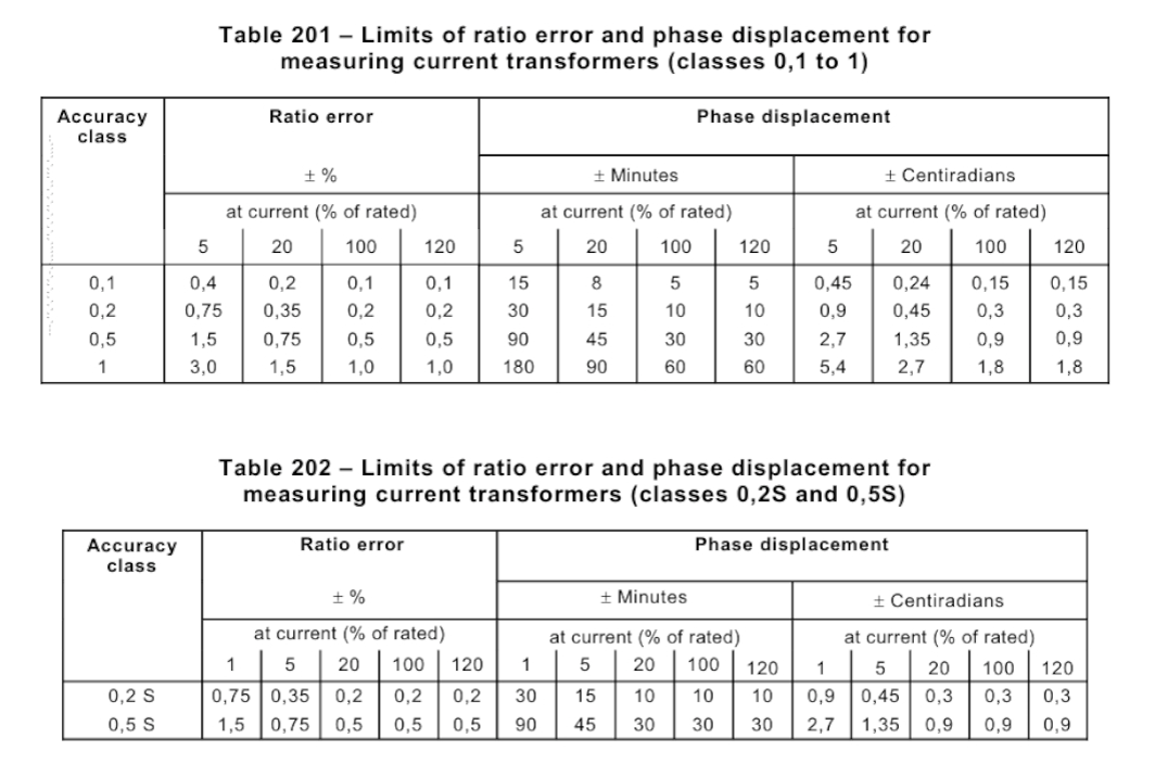
According to international standards, when the secondary current vector leads the ideal position in phase, the phase angle error is positive (+); conversely, when it lags, the phase angle error is negative (-).
This seemingly insignificant angle is crucial for high-precision energy metering.
2. Why do Current Transformers Exhibit Phase Shift?
The root cause of phase angle error lies in the inherent characteristics of the transformer’s physical structure and electromagnetic principles, specifically the presence of the excitation current.
Current transformers operate similarly to transformers: primary current flowing through the core generates a magnetic field, which in turn induces a secondary current.
To establish this necessary magnetic field in the core, the transformer itself consumes a portion of energy. The current corresponding to this energy consumption is the exciting current.
- Magnetizing Component: Used to establish the magnetic field in the core, its phase lags behind the induced electromotive force by 90°.
- Iron loss component: Compensates for energy losses in the core due to hysteresis and eddy currents under alternating magnetic fields. Its phase is in phase with the induced electromotive force.
Since the primary current I₁ equals the vector sum of the secondary current I₂ (converted to the primary side) and the excitation current I₀ (I₁ = I₂ + I₀),
the presence of the non-coincident excitation current I₀ inevitably creates a phase difference between I₁ and I₂.
This phase difference ultimately manifests as the angle difference in the mutual inductor.
Simply put, the angular difference is essentially a “disturbance” in the phase relationship of currents caused by the excitation current.
All factors affecting the magnitude and phase of the excitation current—such as the magnetic properties of the core material, the load (burden) connected to the secondary side, and the magnitude of the primary current itself—directly influence the angular difference.
3. How Does the Angular Difference Affect the Accuracy of Electrical Energy Monitoring?
The formula for calculating electrical energy (active power) is:
P = U × I × cos(φ), where φ is the phase angle between voltage and current, and cos(φ) represents the power factor.
Phase angle error in the transformer directly alters the phase angle φ measured by the energy meter, leading to errors in power calculation.
Error propagation relationship: The total error in energy measurement is approximately equal to the sum of the voltage ratio error, current ratio error, and phase angle error.
A simplified formula can be expressed as:
Power measurement error ≈ Voltage ratio error + Current ratio error + tan(φ) × Δφ
Where Δφ represents the phase angle error introduced by the instrument transformers.
Key Influencing Factor: Power Factor
- High power factor (cos(φ) ≈ 1, φ ≈ 0°): tan(φ) is very small, and the angular error Δφ contributes minimally to the total error. Measurement error is primarily determined by the “ratio error” (amplitude error).
- Low power factor (cos(φ) → 0, φ → ±90°): tan(φ) becomes extremely large. Even a small phase angle error Δφ, amplified by tan(φ), can cause significant power measurement errors.
For example: In a circuit with an extremely low power factor, even if the ratio error (amplitude error) of the instrument transformer is very small,
the final calculated energy reading may still deviate significantly from the true value if any phase angle error exists.
4. Manifestations of Phase Angle Error Impact
- Inductive loads (e.g., motors, transformers with lagging power factor): A positive phase error typically causes the meter reading to exceed actual energy consumption, resulting in unnecessary electricity charges for the user.
- Capacitive loads (e.g., capacitor banks, excessively long cables, leading power factor): A positive phase angle error causes the meter reading to understate actual energy consumption, resulting in losses for the power supplier.
In modern industrial and commercial settings, the widespread use of variable frequency drives, motors, LED lighting, and switching power supplies has made grid power factor increasingly complex and often suboptimal.
Against this backdrop, the phase angle difference of current transformers has evolved from a secondary parameter into a critical factor determining whether an energy monitoring system can operate with “accuracy and fairness.”