
In the huge system of electronic equipment, the power supply is a key part to ensure the stable operation of the equipment. As two common types of power supplies, switching power supply and linear power supply have obvious differences in multiple dimensions, which directly affect the applicability of power supply in different scenarios. Understanding their differences is very important for professional electronic engineers to design circuits or ordinary electronic enthusiasts to maintain and use electronic equipment.
The core of the switching power supply is that the switch tube is turned on and off at high frequency. Take the common Buck step-down circuit as an example:
Conduction phase: When the switch tube is turned on, the input voltage is loaded on the inductor, the inductor begins to store energy, and the current supplies power to the load and charges the output capacitor at the same time, and the inductor current gradually increases.
Turn-off phase: When the switch tube is turned off, the current in the inductor cannot change suddenly, so it will form a loop through the freewheeling diode, continue to supply power to the load, and the inductor current gradually decreases.
Control method: The output voltage is precisely controlled by adjusting the proportion of the switch tube conduction time in the entire switching cycle (i.e., the duty cycle).
For example, converting a 12V input to a 5V output is achieved by adjusting the duty cycle. The operating frequency of the switching power supply is usually between tens of kHz and several MHz. The high-frequency operating characteristics enable it to use miniaturized inductors, capacitors and other energy storage components to effectively improve the power density.
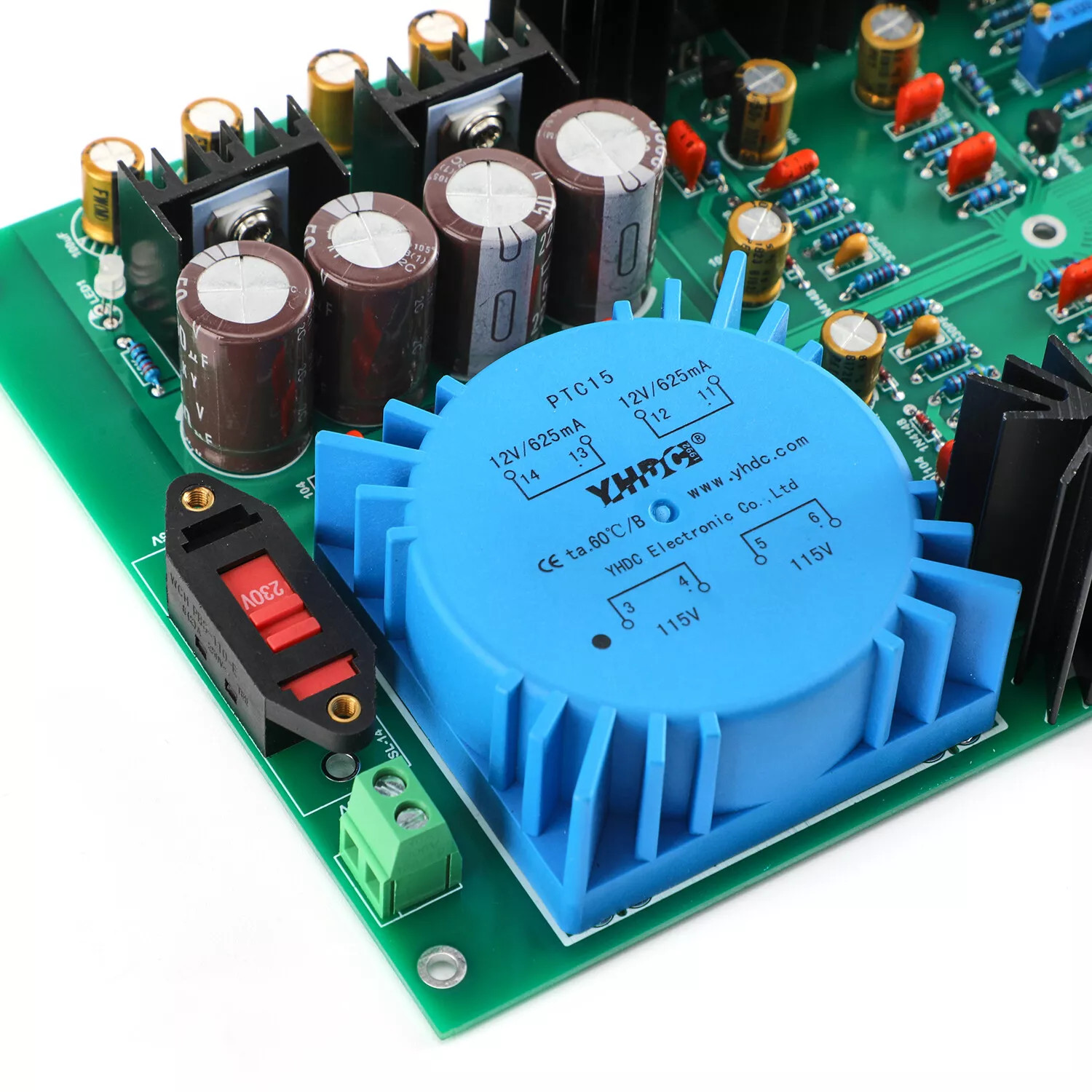
Linear power supplies use the linear amplification characteristics of linear adjustment components (such as Linear Transformer) to stabilize the output voltage:
Basic process: The input AC power is first stepped down by the transformer, and then converted to DC power by the rectifier. After preliminary smoothing by the filter capacitor, the linear adjustment tube continuously adjusts the internal resistance according to the feedback signal to stabilize the output voltage.
Working state: The linear adjustment tube always works in the linear amplification area, and the current passes continuously, ensuring the stability of the voltage adjustment process.
This continuous adjustment method makes the output voltage more stable and is suitable for scenarios with high voltage accuracy requirements.
The efficiency of switching power supply is usually between 70% and 95%, mainly due to the following characteristics:
When turned on: the internal resistance of the switch tube is extremely small, and the heat loss is low when the current passes through.
When turned off: almost no current passes, and the power loss can be ignored.
Only at the moment of switching: a certain loss is generated due to the overlap of voltage and current, but the overall proportion is small.
In high-power applications (such as server power supplies and industrial equipment), the high efficiency characteristics of switching power supplies can significantly reduce energy consumption and save operating costs.
The efficiency of linear power supply is generally between 30% and 60%, mainly because:
The linear adjustment tube needs to continuously consume its own power to adjust the output voltage.
When the input and output voltage difference is large, the power loss on the adjustment tube is significant, and a large amount of electrical energy is wasted in the form of heat energy.
For example, when the input is 12V and the output is 5V, the adjustment tube needs to bear a 7V voltage drop, and this part of the energy is all converted into heat. Therefore, linear power supplies are mostly used in low-power and low-efficiency applications.
Due to its pulsed working mode, the output ripple of the switching power supply is large. Although the ripple can be reduced by adding a filter circuit (such as electrolytic capacitor + ceramic capacitor in parallel), its ripple level is still higher than that of the linear power supply.
Applicable scenarios: Applicable to equipment with low ripple requirements, such as ordinary motor drive power supplies.
Restricted scenarios: Not applicable to circuits with high requirements for power purity, such as precision analog signal processing or high-end audio equipment.
Linear power supply has extremely small output ripple through linear adjustment and smooth filtering, and is suitable for:
High-precision measurement equipment (such as oscilloscopes, medical diagnostic instruments)
Systems with extremely high voltage stability requirements (such as scientific research instruments, precision amplifier circuits)
Switching power supply has a high operating frequency, can use small inductors and capacitors, and does not require large power frequency transformers, so:
Small size and light weight
High power density: can provide higher power at the same volume
Widely used in portable devices (such as mobile phone chargers, tablet power adapters) and systems with strict space requirements.
Linear power supply has a low operating frequency, and requires the use of large-size power transformers and large-capacity filter capacitors, resulting in:
Large size and heavy weight
Not suitable for space-constrained equipment
In occasions such as portable medical equipment and small drones, linear power supplies may be limited by volume issues
Due to the presence of energy storage components such as inductors and capacitors, it takes a certain amount of time to adjust the output voltage when the load changes suddenly. Although the response speed can be improved by optimizing the control circuit, the response speed improvement is limited by the characteristics of the energy storage components.
Applicable scenarios: equipment with infrequent load changes
The linear power supply adjustment tube can quickly adjust the internal resistance and respond to load changes. It is suitable for:
Audio amplifier (need to quickly follow the audio signal)
High-speed data acquisition system
Precision motion control system
Switching power supply will generate high-frequency harmonics during high-frequency on/off, resulting in strong electromagnetic interference (EMI):
Conducted interference: conducted through the power line
Radiated interference: radiated through space
To reduce interference, filtering, shielding, and optimized PCB layout measures are required, which increase the design complexity and cost.
Linear power supply has low operating frequency, and the main sources of electromagnetic interference are transformer leakage and rectifier noise. The interference frequency is low and the intensity is weak, so almost no additional suppression measures are required.
Applicable scenarios: Environments that are sensitive to electromagnetic interference, such as near wireless communication equipment


Copyright © 2024 PowerUC Electronics Co.


