• What Is a Switched-Mode Power Supply (SMPS)?

    What Is a Switched-Mode Power Supply (SMPS)?

    Compared with traditional linear power supplies, switched-mode power supplies (SMPSs) offer higher efficiency and occupy less space, but care must be taken to keep output noise at a low level.

    Overview of Switched-Mode Power Supplies

    Switched-mode power supplies are widely used because of their advantages in size, weight, cost, efficiency, and overall performance.

    Thanks to these performance advantages, switched-mode power supplies are used in most types of electronic systems to provide efficient and effective power, except in the most demanding applications.

    Switched-mode power supplies have become a widely accepted part of electronic technology. They are also commonly referred to as switched-mode power converters, or simply as “switchers.”

    Switched-Mode Power Supply Terminology

    Several closely related terms are used for switched-mode power supply (SMPS) technology. Although they all refer to the same basic technology, they describe different parts of the overall system.

    • Switched-mode power supply (SMPS): This term usually refers to a complete unit that connects to the mains supply or another external power source and produces a regulated output. In other words, it is a complete power supply.
    • Switching regulator: This usually refers only to the electronic circuit that performs the voltage-regulation function. A switching regulator is one part of a complete switched-mode power supply.
    • Switching regulator controller: Many switching-regulator integrated circuits do not include the series switching element. This is especially true in higher-current or higher-voltage applications, where an external series switching element is better able to withstand the current, voltage, and resulting power dissipation.

    Switched-Mode Power Supply Fundamentals

    The basic concept of a switched-mode power supply (SMPS) is to use a switching regulator to control the output voltage. It employs a series switching element that periodically turns the current flowing to a smoothing capacitor on and off.

    The on-time of the series element is controlled by the voltage across the capacitor. If the voltage rises above the required value, the series switching element turns off; if the voltage falls below the required value, it turns on. In this way, the voltage across the smoothing or energy-storage capacitor is maintained at the required level.

    Principle of Operation of a Switching Regulator

    Open this circuit in EveryCircuit

    Advantages and Disadvantages of Switched-Mode Power Supplies

    Any technology generally requires a careful assessment of its advantages and disadvantages. Switched-mode power supplies are no exception: they offer several clear benefits, but they also have limitations.

    Advantages of Switched-Mode Power Supplies

    • High efficiency: Because of the switching mode of operation, the series regulating element is either on or off. Very little energy is therefore dissipated as heat, enabling very high efficiency.
    • Compact design: High efficiency and low heat-dissipation requirements allow switched-mode power supplies to be made more compact.
    • Cost: Cost is one of the most attractive aspects of switched-mode power supplies. Their high efficiency and switching design mean that they dissipate less heat than linear power supplies, which helps reduce cost. In addition, switching operation allows many components to be implemented using lower-cost devices.
    • Technical flexibility: Switched-mode power supply technology can be used in both boost and buck applications, enabling efficient voltage conversion.

    Disadvantages of Switched-Mode Power Supplies

    • Noise: The transient spikes generated during switching are one of the main drawbacks of switched-mode power supplies. If these spikes are not properly filtered, they may propagate to different parts of the circuitry powered by the SMPS. The spikes or transient disturbances may also produce electromagnetic interference or radio-frequency interference that affects nearby electronic equipment, especially radio receivers.
    • External components: Although a switching regulator can be designed around a single integrated circuit, external components are usually still required. The most obvious is the energy-storage capacitor, and filtering components are also needed. In some designs, the series switching element can be integrated into the chip, but where a certain amount of current must be delivered, the series switch is usually an external component. These components occupy space and add cost.
    • Specialist design expertise required: Building a switched-mode power supply that operates is usually not difficult, but ensuring that it meets the specified performance requirements can be more challenging. In particular, keeping ripple and interference within required limits can be quite demanding.
    • Filtering: The filtering of a switched-mode power supply must be designed carefully, because poor filter design can result in high levels of noise and spikes at the output.
  • Wie schließt man einen Stromschalter an ein Relais, eine SPS, einen NPN- oder PNP-Eingang an?

    Wie schließt man einen Stromschalter an ein Relais, eine SPS, einen NPN- oder PNP-Eingang an?

    Ein Stromschalter wird häufig in der industriellen Automatisierung, der Anlagenüberwachung und der Erkennung des Lastzustands eingesetzt. Er erkennt, ob Strom durch einen Leiter fließt, und gibt ein Schaltsignal an ein Relais, eine SPS oder ein Steuerungssystem aus.

    Was ist ein Stromschalter?

    Ein Stromschalter ist ein Sensor, der den Strom in einem Leiter erkennt und ein Schaltsignal ausgibt.

    Er dient normalerweise nicht zur Messung genauer Stromwerte, sondern zur Feststellung, ob der Strom einen voreingestellten Schwellenwert überschreitet. Beispielsweise kann ein Stromschalter mit festem 2-A-Schwellenwert ein Signal ausgeben, wenn der gemessene Strom etwa 2 A erreicht, und damit bestätigen, dass die Last angelaufen ist.

    Im Gegensatz zu Stromwandlern und Strommessumformern ist das wichtigste Ausgangssignal eines Stromschalters ein digitales Signal.

    Vergleich der Produkttypen

    ProdukttypÜblicher AusgangHauptanwendungen
    StromschalterNPN, PNP, Transistoren, MOSFETs oder RelaiskontakteFeststellung, ob eine Last läuft oder stillsteht
    StromwandlerWechselstromsignale mit 1 A, 5 A oder im MilliamperebereichStrommessung und Schutz
    Strommessumformer4–20 mA, 0–10 VKontinuierliche Strommessung
    StromüberwachungsrelaisRelaiskontakteÜberstrom-, Unterstrom- und Fensterüberwachung

    Überblick über den Stromschalter JWY-297

    Der JWY-297 ist ein Wechselstromschalter, der keine zusätzliche Stromversorgung benötigt und erkennt, ob Strom durch einen Leiter fließt.

    Wenn der Strom im überwachten Leiter den Schaltpunkt von etwa 2 A überschreitet, schaltet der interne Transistor durch. So lässt sich der „Betriebszustand des Geräts“ digital erfassen.

    Sein Ausgang ist ein NPN-Ausgang mit offenem Kollektor. Daher sind je nach Steuerungssystem unterschiedliche Anschlussarten erforderlich.

    Wichtig: Ein NPN-Ausgang mit offenem Kollektor gibt nicht selbst eine positive Spannung aus. Wenn Strom erkannt wird, zieht er die Signalleitung auf 0 V.

    1. Anschluss an eine Relaislast

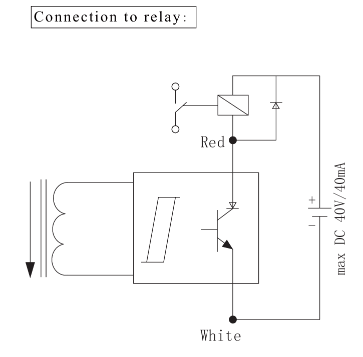
    Der STWA1S kann kleine Gleichstromrelais direkt ansteuern, sofern der Strom der Relaisspule innerhalb der Ausgangsbelastbarkeit liegt, beispielsweise bei höchstens 40 V DC / 40 mA. Wenn Strom erkannt wird, schaltet der Ausgangstransistor durch und zieht ein Ende der Relaisspule auf Masse. Dadurch zieht das Relais an.

    Connecting current switch to relay load
    Wiring diagram: current switch connected to a relay load

    Geeignete Einsatzbereiche

    • Einfache Betriebsanzeige für Geräte
    • Eigenständige Steuerungssysteme ohne SPS
    • Ein/Aus-Überwachung kleiner Pumpen, Lüfter und Heizgeräte

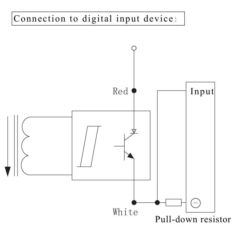
    2. Anschluss an einen stromliefernden SPS-Eingang – Pull-down-Schaltung

    Stromliefernde Eingangsmodule stellen eine interne Pull-up-Spannung bereit, üblicherweise +24 V. Da der Ausgang des STWA1S die Signalleitung nur auf einen niedrigen Pegel ziehen kann, kann er den SPS-Eingang direkt auf 0 V ziehen und so das Signal auslösen.

    Connecting current switch to PLC sourcing input pull-down configuration
    Wiring diagram: current switch connected to PLC sourcing input

    Merkmale

    • Keine externen Widerstände erforderlich
    • Sehr einfache Verdrahtung
    • Kompatibel mit den meisten modernen SPS-Systemen, etwa gängigen Digitaleingangsmodulen von Siemens, Omron und Mitsubishi

    Anwendungen

    • Überwachung des Betriebszustands von Automatisierungssystemen
    • Erkennung, ob Lüfter, Pumpen oder Heizgeräte laufen
    • Mehrkanalige Stromerkennung mit paralleler ODER-Verknüpfung

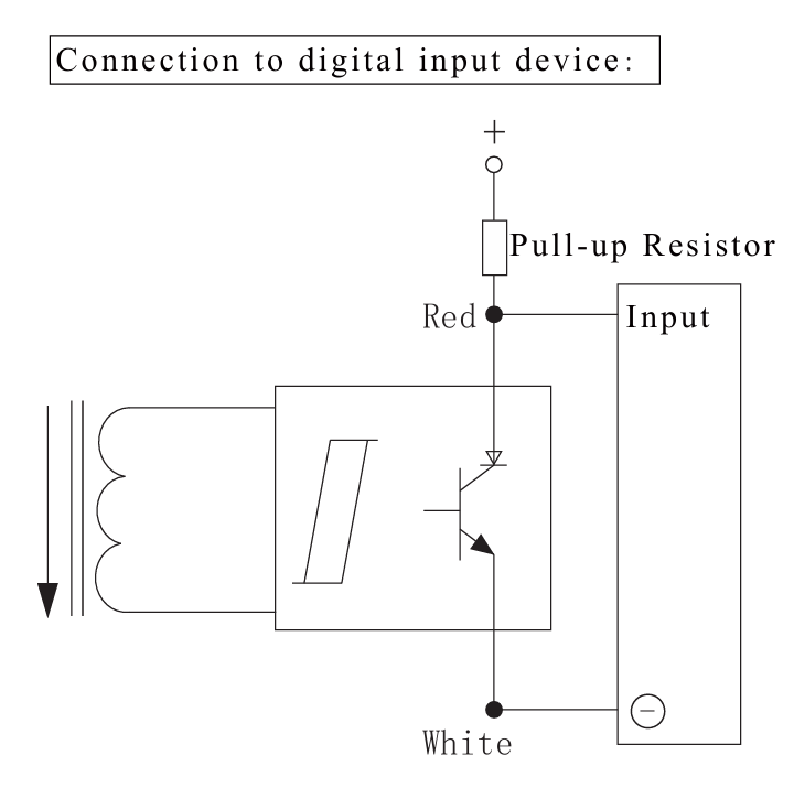
    3. Anschluss an einen stromaufnehmenden SPS-Eingang – Pull-up-Schaltung

    Stromaufnehmende Eingangsmodule verfügen über eine interne Pull-down-Schaltung und benötigen eine externe Pull-up-Spannung. In diesem Fall muss am Ausgang des STWA1S ein Pull-up-Widerstand ergänzt werden, damit am SPS-Eingang ein hoher Pegel anliegt.

    Connecting current switch to PLC sinking input pull-up configuration
    Wiring diagram: current switch connected to PLC sinking input with pull-up resistor

    Merkmale

    • Erfordert einen externen Pull-up-Widerstand, üblicherweise 2,2 kΩ–10 kΩ
    • Geeignet für ältere SPS-Systeme oder spezielle Steuerplatinen

    Geeignete Einsatzbereiche

    • Digitaleingänge auf industriellen Steuerplatinen
    • Ältere SPS-Modelle, etwa einige S5-Modelle und frühe inländische SPS-Systeme

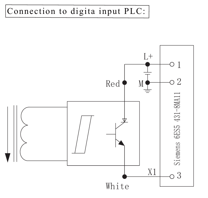
    4. Anschluss an integrierte Digitalmodule wie Siemens S5

    Module wie das Siemens 6ES5 431 8MA11 stellen bereits eine interne Pull-up-Spannung bereit. Daher kann die übliche Anschlussart für den STWA1S direkt verwendet werden.

    • Rotes Kabel → Eingangsklemme, zum Beispiel X1
    • Schwarzes Kabel → Gemeinsame Klemme, M
    Connecting current switch to Siemens S5 built-in digital module
    Wiring diagram: current switch connected to Siemens S5 digital input module

    Geeignete Einsatzbereiche

    • Nachrüstung älterer Anlagen
    • Überwachung des Betriebszustands von S5-Systemen
    • Modernisierung bestehender Anlagen in Serverräumen, Gebäuden und Fabriken

    Zusammenfassung

    Ein Stromschalter bietet eine einfache und zuverlässige Möglichkeit, zu erkennen, ob eine Last läuft oder stillsteht. Im Vergleich zu Stromwandlern und Strommessumformern dient er der Erkennung des Schaltzustands statt der genauen Strommessung.

    Zur Relaissteuerung kann er kleine Gleichstromrelaisspulen innerhalb seiner zulässigen Ausgangsbelastbarkeit direkt ansteuern. Bei SPS-Systemen hängt die Verdrahtung davon ab, ob das Eingangsmodul stromliefernd oder stromaufnehmend ist. Bei integrierten Digitalmodulen wie Siemens S5 lässt sich der Stromschalter oft direkt anschließen, wenn das Modul bereits eine interne Pull-up-Spannung bereitstellt.

    Hinweis zur Auswahl: Prüfen Sie vor der Verdrahtung den Ausgangstyp des Stromschalters, den SPS-Eingangstyp, die Versorgungsspannung und den maximal zulässigen Ausgangsstrom, um einen zuverlässigen Betrieb sicherzustellen und Schäden am Steuerkreis zu vermeiden.

    “`

  • Unterschiede und Anwendungen von Strommessumformern mit RMS- und TRMS-Ausgang

    Unterschiede und Anwendungen von Strommessumformern mit RMS- und TRMS-Ausgang

    In der industriellen Automatisierung, im Energiemanagement und bei der Zustandsüberwachung von Anlagen werden Strommessumformer häufig eingesetzt, um primärseitigen Wechselstrom in standardisierte Gleichsignale wie 0–1 V, 0–5 V, 0–10 V oder 4–20 mA umzuwandeln. Diese können von SPS, Messgeräten oder Datenerfassungssystemen einfach verarbeitet werden.

    Je nachdem, wie der Effektivwert verarbeitet wird, werden diese Messumformer üblicherweise in Ausführungen mit RMS-Ausgang und TRMS-Ausgang eingeteilt. Beide können den Effektivwert des primärseitigen Stroms als Gleichsignal darstellen, unterscheiden sich jedoch erheblich darin, welche Eingangswellenformen sie verarbeiten können.

    Hinweis: „DC-RMS-Ausgang“ bedeutet nicht, dass die Gleichstromkomponente gemessen wird. Vielmehr wird der Effektivwert des Wechselstroms durch ein Gleichspannungs- oder Gleichstromsignal dargestellt.

    I. Bedeutung des Strom-Effektivwerts (RMS)

    Der Effektivwert (RMS) eines Wechselstroms beschreibt dessen Wärmewirkung an einer ohmschen Last und entspricht hinsichtlich dieser Wirkung einem Gleichstrom bestimmter Stärke.

    Er ist wie folgt definiert:

    rms_definition_formula

    Bei einer idealen Sinuswelle gilt für das Verhältnis zwischen dem Effektivwert und dem Spitzenwert des Stroms:

    rms_peak_formula

    Strommessumformer wandeln den gemessenen Effektivwert in ein analoges Gleichsignal um. Bei einem Messumformer mit einem Messbereich von 0–100 A und einem Ausgang von 4–20 mA beträgt das theoretische Ausgangssignal bei einem primärseitigen Strom von 50 A beispielsweise etwa 12 mA.

    II. Strommessumformer mit RMS-Ausgang

    In der Praxis übliche Messumformer mit RMS-Ausgang arbeiten meist durch Gleichrichtung, Filterung und Mittelwertbildung des Eingangssignals. Der Messumformer ermittelt zunächst den Mittelwert der gleichgerichteten Wechselstromwellenform und rechnet ihn anschließend anhand eines festen, auf einer idealen Sinuswelle beruhenden Faktors in den Effektivwert um.

    Dieses Verfahren benötigt eine vergleichsweise einfache Schaltung und bietet Vorteile wie geringe Kosten, gute Stabilität und ein gleichmäßiges Ansprechverhalten. Bei sinusförmigen Strömen mit Netzfrequenz oder Wechselströmen mit geringer Verzerrung liefert es gute Messergebnisse.

    Dieses Umrechnungsverhältnis setzt jedoch voraus, dass die Eingangswellenform annähernd sinusförmig ist. Bei Begrenzung, Phasenanschnitt, Impulsen oder ausgeprägten Oberschwingungen verändert sich das Verhältnis zwischen dem gleichgerichteten Mittelwert und dem tatsächlichen Effektivwert. Dadurch kann das Ausgangssignal des Messumformers erhebliche Fehler aufweisen.

    Geeignete Anwendungen für Strommessumformer mit RMS-Ausgang

    • Stromverteilungskreise mit Netzfrequenz
    • Herkömmliche ohmsche Heizgeräte
    • Motoren, Lüfter und Pumpen mit Netzfrequenz
    • Beleuchtungsstromkreise
    • Wechselstromlasten mit geringer Wellenformverzerrung
    • Projekte, bei denen vor allem der Betriebszustand und die Lastentwicklung überwacht werden

    Typische Anwendungen von Produkten mit RMS-Ausgang

    Der YHDC SCT016T-D beispielsweise hat eine selbstversorgte, teilbare Bauform nach dem Stromwandlerprinzip. Nach Gleichrichtung und Filterung des Sekundärsignals liefert er 0–1 V DC oder 0–5 V DC. Er benötigt keine externe Stromversorgung und eignet sich für die Nachrüstung von Verteilerschränken, die Überwachung des Energieverbrauchs von Gebäuden und die Erfassung der Betriebsströme allgemeiner Geräte.

    Für die Übertragung über größere Entfernungen kann der teilbare Zweidraht-Messumformer TST016T die Messergebnisse in ein 4–20-mA-Signal umwandeln. Die Zweidrahtschnittstelle ermöglicht eine einfache Verdrahtung und ist wenig störanfällig. Damit eignet sie sich für den Anschluss an SPS und industrielle Steuerungssysteme.

    Für die zentrale Installation in Schaltschränken bietet der YHDC TCAH eine geschlossene Bauform und die Montage auf einer Hutschiene. Als Ausgänge stehen 4–20 mA oder 0–10 V zur Verfügung. Er eignet sich für neue Stromverteilerschränke, Komplettanlagen und die Überwachung üblicher Lasten mit Netzfrequenz.

    Für Sammelschienen mit hohen Strömen, dicke Kabel oder Anwendungen mit wenig Einbauraum kann eine Rogowski-Spule eingesetzt werden. Die YHDC TRV02-Serie von Integratoren für Rogowski-Spulen liefert 4–20 mA oder 0–1 V. Sie eignet sich für die Messung an Sammelschienen mit Netzfrequenz, leistungsstarken Heizgeräten und Wechselstromsignalen mit hohen Strömen und annähernd sinusförmiger Wellenform.

    III. Strommessumformer mit TRMS-Ausgang

    TRMS steht für True Root Mean Square, also den echten Effektivwert. TRMS-Messumformer verarbeiten den Eingangsstrom durch Quadrieren, Mittelwertbildung und anschließendes Ziehen der Quadratwurzel entsprechend der Definition des Effektivwerts. Daher können sie neben idealen Sinuswellen auch verschiedene nicht sinusförmige Wellenformen messen.

    Solange Amplitude, Frequenz und Scheitelfaktor des Eingangsstroms innerhalb der für das Produkt angegebenen Grenzen liegen, können TRMS-Messumformer die tatsächliche Wärmewirkung verzerrter Ströme genauer abbilden.

    Geeignete Anwendungen für Messumformer mit TRMS-Ausgang

    • Ein- und Ausgangsklemmen von Frequenzumrichtern
    • Systeme mit unterbrechungsfreier Stromversorgung und Wechselrichter
    • Gleichrichter und Schaltnetzteile
    • Thyristorgesteuerte Leistungsregler
    • Schweiß- und Induktionserwärmungsanlagen
    • Nichtlineare Lasten mit vielen Oberschwingungen
    • Begrenzte, gepulste oder nur zeitweise fließende Ströme

    Typische Anwendungen von Produkten mit TRMS-Ausgang

    Der YHDC THT2032 beispielsweise verfügt über eine geschlossene Bauform und liefert 4–20 mA oder 0–10 V. Er eignet sich für den Einbau in neue Schaltschränke oder Komplettanlagen. Im Vergleich zu herkömmlichen RMS-Messumformern eignet er sich besser für Frequenzumrichter, Sanftanlasser, Systeme mit unterbrechungsfreier Stromversorgung, Gleichrichternetzteile und Thyristorlasten.

    Für Anwendungen mit hohen Strömen oder solche, bei denen herkömmliche Messumformer mit geschlossenem Kern unpraktisch sind, können die Hall-Stromintegratoren der Serie YHDC TRS02 eingesetzt werden. Diese Serie liefert Ausgangssignale von 4–20 mA oder 0–1 V und kann verzerrte, gepulste und oberschwingungsreiche Wechselströme genauer messen. Sie eignet sich damit für Frequenzumrichter, Wechselrichter, Schweißgeräte und Sammelschienen mit hohen Strömen.

    Hinweis: Rogowski-Spulen können keinen konstanten Gleichstrom messen. TRMS bezeichnet die Berechnung des echten Effektivwerts einer zeitlich veränderlichen Stromwellenform. Das bedeutet nicht zwangsläufig, dass das Produkt den echten Effektivwert von Wechselstrom mit Gleichstromanteil messen kann.

    IV. Wesentliche Unterschiede zwischen RMS- und TRMS-Ausgängen

    Der wesentliche Unterschied liegt nicht in der Ausgangsschnittstelle. Sowohl RMS- als auch TRMS-Produkte können Gleichspannungs- oder 4–20-mA-Signale ausgeben. Entscheidend ist, wie der Messumformer den Effektivwert des Eingangsstroms intern berechnet.

    VergleichskriteriumMessumformer mit RMS-AusgangMessumformer mit TRMS-Ausgang
    Verfahren zur EffektivwertbestimmungÜblicherweise wird der gleichgerichtete Mittelwert gemessen und anhand des Verhältnisses für Sinuswellen umgerechnet.Der echte Effektivwert wird durch Quadrieren, Mittelwertbildung und anschließendes Ziehen der Quadratwurzel berechnet.
    Messung von SinuswellenGenauGenau
    Messung verzerrter WellenformenKann zu erheblichen Fehlern führen.Ist in der Regel genauer.
    Geeignete LastenLineare oder wenig verzerrende Lasten wie Motoren mit Netzfrequenz, Heizungen und Beleuchtung.Frequenzumrichter, Gleichrichter, Systeme mit unterbrechungsfreier Stromversorgung und andere nichtlineare Lasten.
    SchaltungsaufwandGeringHoch
    ProduktkostenIn der Regel geringIn der Regel hoch
    BeispielprodukteSCT016T-D, TST016T, TRV02, TCAHTHT2032, TRS02

    V. Typische Anwendungsszenarien

    Herkömmliche Stromverteilungssysteme mit Netzfrequenz

    Bei Anwendungen mit stabiler Netzfrequenz, deren Lasten überwiegend aus ohmschen und induktiven Verbrauchern sowie herkömmlichen Motoren mit Netzfrequenz bestehen, ist die Stromwellenform meist annähernd sinusförmig. Ein Messumformer mit RMS-Ausgang reicht dann für die Überwachung aus.

    Für die Nachrüstung bestehender Stromverteilungskreise können die teilbaren Modelle SCT016T-D oder TST016T verwendet werden. Für die zentrale Installation in Schaltschränken eignet sich der geschlossene, auf einer Hutschiene montierte TCAH. Für Sammelschienen mit hohen Strömen kann der TRV02 zusammen mit einer Rogowski-Spule eingesetzt werden.

    Frequenzumrichtersysteme

    Am Ausgang von Frequenzumrichtern liegt üblicherweise eine PWM-modulierte Wellenform an. Der Strom kann erhebliche hochfrequente Anteile und Oberschwingungen enthalten. Herkömmliche RMS-Messumformer bilden den tatsächlichen Effektivwert möglicherweise nicht genau ab. Deshalb sollten TRMS-Produkte bevorzugt werden.

    Für neue Anlagen mit kleinen bis mittleren Strömen kann der geschlossene THT2032 verwendet werden. Für Sammelschienen mit hohen Strömen, dicke Kabel oder beengte Einbauverhältnisse eignen sich die Integratoren für Rogowski-Spulen der Serie TRS02.

    Thyristorgesteuerte Leistungsregler

    Thyristoren regeln die Ausgangsleistung, indem sie den Leitwinkel in jeder Periode verändern. Obwohl die Grundfrequenz des Stroms weiterhin 50 Hz oder 60 Hz beträgt, ist die Wellenform nicht mehr rein sinusförmig.

    In solchen Fällen können herkömmliche RMS-Messumformer erhebliche Messfehler verursachen. Deshalb sollten Messumformer mit TRMS-Ausgang wie die Serien THT2032 oder TRS02 eingesetzt werden.

    Überwachung des Energieverbrauchs und Beurteilung des Anlagenzustands

    Wenn das Stromsignal vor allem dazu dient, festzustellen, ob eine Anlage läuft oder stillsteht, oder Lastverläufe zu analysieren, und die gemessene Wellenform relativ stabil ist, sind RMS-Produkte in der Regel wirtschaftlicher.

    Wenn die Messergebnisse zur Beurteilung der Leitererwärmung, des Lastfaktors, von Überlastzuständen oder des Betriebs frequenzgeregelter Geräte verwendet werden, liefern TRMS-Produkte zuverlässigere Effektivwertdaten.

    VI. Zusammenfassung

    Sowohl RMS- als auch TRMS-Strommessumformer können primärseitigen Wechselstrom in ein standardisiertes Gleichsignal umwandeln. Sie unterscheiden sich jedoch darin, welche Eingangswellenformen sie verarbeiten können.

    Für Lasten mit annähernd sinusförmigem Stromverlauf, etwa in herkömmlichen Stromverteilungssystemen mit Netzfrequenz, bei ohmschen Heizungen, Beleuchtung und Motoren mit Netzfrequenz, können Produkte mit RMS-Ausgang wie SCT016T-D, TST016T, TRV02 oder TCAH gewählt werden, um Messanforderungen und Betriebskosten in Einklang zu bringen.

    Bei Frequenzumrichtern, Systemen mit unterbrechungsfreier Stromversorgung, Wechselrichtern, Gleichrichtern, thyristorgesteuerten Leistungsreglern, Schweißgeräten und anderen nichtlinearen Lasten sollten Produkte mit TRMS-Ausgang wie THT2032 oder TRS02 bevorzugt werden. Ihr gemessener Strom-Effektivwert bildet die tatsächliche Wärmewirkung besser ab.

    Empfehlung zur Auswahl: Stellen Sie bei der Wahl eines Modells zuerst fest, ob der zu messende Strom eine ideale Sinuswellenform aufweist. Bei annähernd sinusförmigem Verlauf genügt ein RMS-Produkt. Weist die Wellenform deutliche Verzerrungen, Impulse oder Oberschwingungen auf, sollte ein TRMS-Produkt gewählt werden.

  • Wie wandelt man Signale einer 4–20-mA-Stromschleife in Spannungssignale um?

    Wie wandelt man Signale einer 4–20-mA-Stromschleife in Spannungssignale um?

    Die 4–20-mA-Stromschleife ist ein häufig verwendetes Verfahren zur Übertragung analoger Signale in der industriellen Automatisierung. Dieser Artikel erklärt die Grundlagen der 4–20-mA-Stromschleife, die Umwandlung von Strom in Spannung und die Auswahl eines geeigneten Messwiderstands.

    I. Grundlagen der 4–20-mA-Stromschleife

    Die 4–20-mA-Stromschleife ist ein häufig verwendetes Verfahren zur Übertragung analoger Signale in der industriellen Automatisierung. YHDC stellt verschiedene Strommessumformer und Spannungsmessumformer in unterschiedlichen Bauformen und mit unterschiedlichen Kenndaten her.

    Bei diesem Signal entsprechen 4 mA dem unteren Messbereichsende, also 0 %, und 20 mA dem oberen Messbereichsende, also 100 %.

    Da das Signal bei 4 mA statt bei 0 mA beginnt, kann das System bei einem Strom unter 4 mA erkennen, ob ein Leitungsbruch oder eine Störung vorliegt.

    II. Umwandlung von Strom in Spannung

    Die einfachste Möglichkeit, ein 4–20-mA-Stromsignal in ein Spannungssignal umzuwandeln, besteht darin, einen Präzisionswiderstand in Reihe in den Stromkreis einzuschalten. Dieser Widerstand wird üblicherweise als Messwiderstand oder Lastwiderstand bezeichnet.

    Nach dem ohmschen Gesetz gilt:

    V = I × R

    Dabei gilt:

    • V bezeichnet die Spannung am Widerstand.
    • I bezeichnet den Strom durch den Widerstand.
    • R bezeichnet den Widerstandswert des Messwiderstands.

    Wenn der Strom durch den Messwiderstand fließt, fällt an ihm eine entsprechende Spannung ab. Je größer der Strom, desto höher die Spannung.

    III. Auswahl gängiger Widerstandswerte

    Die Genauigkeit des Messwiderstands wirkt sich direkt auf die Messgenauigkeit aus. Empfohlen wird ein Präzisionswiderstand mit 0,1 % Genauigkeit.

    In der Praxis wird häufig ein 250-Ω-Präzisionswiderstand verwendet, um ein 4–20-mA-Stromsignal in ein 1–5-V-Spannungssignal umzuwandeln.

    StromFormelAusgangsspannung
    4 mAV = 0,004 A × 250 Ω1 V
    20 mAV = 0,02 A × 250 Ω5 V

    Wenn das 4–20-mA-Stromsignal durch einen 250-Ω-Widerstand fließt, entsteht somit ein 1–5-V-Spannungssignal.

    IV. Auswahl der Widerstandsbelastbarkeit

    Auch die Belastbarkeit des Widerstands ist sehr wichtig. Damit ein Temperaturanstieg im Widerstand dessen Widerstandswert nicht verändert, wird empfohlen, eine Belastbarkeit zu wählen, die mindestens zehnmal so hoch ist wie die berechnete Verlustleistung.

    Die Formel zur Berechnung der Leistung lautet:

    P = I² × R

    Beispiel für einen 250-Ω-Widerstand bei 20 mA:

    P = 0,02² × 250 × 10 = 1 W

    MesswiderstandAusgangsspannungsbereichEmpfohlene Widerstandsbelastbarkeit
    100 Ω0,4–2 V0,4 W
    250 Ω1–5 V1 W
    500 Ω2–10 V2 W
  • Faktoren, die die Genauigkeit von Rogowski-Spulen beeinflussen

    Faktoren, die die Genauigkeit von Rogowski-Spulen beeinflussen

    Obwohl Rogowski-Spulen viele Vorteile bieten, können mehrere Faktoren ihre Genauigkeit beeinflussen:

    Positionierung und Ausrichtung: Ein solcher Faktor ist die relative Position der Rogowski-Spule zum Leiter. Die korrekte Ausrichtung muss sichergestellt werden, beispielsweise indem die Spule flach und senkrecht zur Stromrichtung angeordnet wird. Andernfalls kann die Messgenauigkeit nicht gewährleistet werden. Diese Empfindlichkeit gegenüber der Positionierung kann Fehler von bis zu 3 % verursachen. Dadurch kann sich der Gesamtfehler bei Messungen mit Stromwandlern (CT) schnell mehr als verdoppeln.

    Leitergröße und Abstand: Die Abmessungen des zu messenden Leiters in der Ebene der Rogowski-Spule beeinflussen die Messgenauigkeit. Ist die Spule zu klein, um alle magnetischen Feldlinien zu erfassen, fallen die Messwerte zu niedrig aus.

    Äußere Störeinflüsse:

    Benachbarte Geräte, die elektromagnetische Störungen (EMI) verursachen, können die Messergebnisse des Sensors beeinflussen. Bewährte Verfahren für Abschirmung und Installation müssen genau eingehalten werden.

    Temperaturänderungen:

    Temperaturänderungen beeinflussen die elektrischen Eigenschaften sowohl der Rogowski-Spule als auch des Leiters und können dadurch zu Messungenauigkeiten führen.

    Anforderungen an den Integrator:

    Das Ausgangssignal der Rogowski-Spule muss durch eine Integratorschaltung verarbeitet werden, um eine nutzbare Stromwellenform zu erhalten.


  • Sind Stromwandler mit teilbarem Kern für Wohngebäude geeignet?

    Sind Stromwandler mit teilbarem Kern für Wohngebäude geeignet?

    Ja, Stromwandler mit teilbarem Kern (CTs) eignen sich für Anwendungen in Wohngebäuden und sind zudem Industriestandard für die Energieüberwachung zu Hause und Nachrüstprojekte.

    Warum sie sich ideal für Wohngebäude eignen

    Die wichtigsten Gründe für ihren Einsatz in Wohngebäuden sind **einfache Handhabung und Sicherheit**. Im Hausverteiler steht die Hauptleitung stets unter Spannung, sofern der Energieversorger den Zähler nicht abklemmt. Stromwandler mit teilbarem Kern lassen sich am Leiter befestigen, ohne den Stromkreis zu unterbrechen.

    1. Installation ohne Eingriff in den Stromkreis

    Um einen Stromwandler mit geschlossenem Kern zu installieren, müssen Sie die Hauptleitung abklemmen, den Leiter durch einen “Ring” führen und ihn anschließend wieder anschließen. Das ist gefährlich und erfordert in der Regel eine vollständige Stromabschaltung. Einen Stromwandler mit teilbarem Kern klemmen Sie dagegen einfach um den isolierten Leiter.

    2. Sicherheit (Niederspannungsausgang)

    Die meisten Stromwandler mit teilbarem Kern für Wohngebäude sind darauf ausgelegt, eine sehr niedrige Spannung auszugeben (typischerweise **0,333 V**) statt eines Stromsignals. Das erhöht die Sicherheit erheblich: Wird ein herkömmlicher Stromwandler mit Stromausgang bei stromführendem Leiter abgeklemmt, kann ein Hochspannungslichtbogen entstehen. Stromwandler mit teilbarem Kern und Spannungsausgang sind für Heimwerker und Hausautomationssysteme besser geeignet.

    3. Kompakte Bauform für Verteilerkästen

    Moderne Stromwandler mit teilbarem Kern sind schlank gebaut. Selbst in vollen Verteilerkästen bieten die Hauptleitung oder einzelne Abzweigleitungen meist genügend Spielraum für die Installation kleiner Sensoren.

  • Why are current transducers so important in chillers, air compressors, and generators?

    Why are current transducers so important in chillers, air compressors, and generators?


    In industrial systems, chillers, air compressors, and generators may seem to belong to different fields, but they share one commonality: their core components are all electric motors. This is why high‑quality current transducers play a critical role in monitoring these systems, ensuring accurate and reliable current measurement.


    And the most direct and accurate indicator of a motor’s operating condition is—current.

    To capture this signal effectively, current transducers (also known as current transmitter or current monitoring transducers) are widely used in industrial equipment.


    Why “Current” Is the Most Valuable Industrial Signal

    Industrial equipment can measure many parameters: voltage, temperature, pressure, flow rate, vibration, and more.

    However, for equipment centered around electric motors, current best reflects the true operating condition, which is why motor current transducers are essential for accurate diagnostics.


    By monitoring current using industrial current transducers, you can quickly determine:

    – Whether the equipment is running

    – Whether it is overloaded

    – Whether it is underloaded or running at no load

    – Whether efficiency has decreased

    – Whether there are signs of potential failure


    Chiller Example

    For example: In water-cooled units, excessively high startup current may indicate mechanical binding or an electrical fault, while abnormally low current may indicate insufficient refrigerant or a compressor running unloaded.

    These conditions are easily detected by current transducers for chillers, which provide real‑time current signatures for fault analysis.


    Air Compressor Example

    In air compressor applications, large current fluctuations may indicate an unstable unloaded system or leaks in the piping network, while excessively high unloaded current may indicate internal wear or abnormal resistance.

    Using current transducers for air compressors helps maintenance teams identify these issues early and improve system reliability.


    Although not explicitly detailed above, generators also rely heavily on current transducers for generators to monitor load variations, detect abnormal current draw, and ensure stable operation.

  • Why are overloaded operation of current transformers prohibited?

    Why are overloaded operation of current transformers prohibited?


    Operating current transformers (CTs) under overload conditions is forbidden because it severely impacts measurement accuracy, equipment integrity, and safety. While short-term overloads (up to 10 times the rated current) may be acceptable, sustained overloads can lead to a variety of serious failures.

    1. Measurement error and core saturation

    Excessive primary current causes an increase in magnetic flux density, leading to core saturation. Once saturated, the relationship between the primary and secondary currents becomes nonlinear, resulting in waveform distortion and measurement errors. Overloading can also induce residual magnetism in the core, affecting the current and phase angle of the current transformer and reducing the accuracy of subsequent measurements.

     2. Equipment damage and performance degradation

    Overloading increases the temperature of the windings. The heat generated by the windings is proportional to the square of the current (I²R loss); for example, a 10% overcurrent increases heat generation by approximately 21%. High temperatures accelerate the chemical decomposition of insulation materials. For every 6–8°C increase in temperature, the insulation’s service life is halved. Prolonged exposure to high temperatures can cause the insulation to melt, resulting in internal short circuits and ultimately leading to the complete burnout of the current transformer.

    3. Serious safety hazards

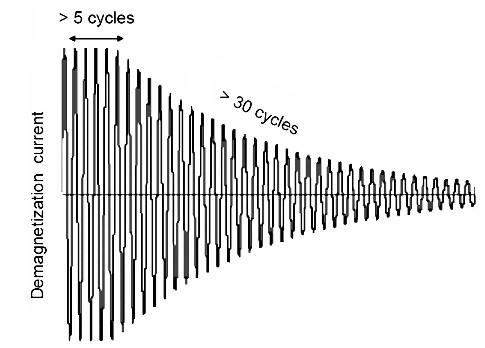
    The dielectric strength of the insulating medium will decrease due to aging or damage caused by high temperature. Severe overheating or internal arcing faults may cause the current transformer to explode or ignite surrounding materials. In extreme cases, overload will cause the secondary circuit to open, which will cause the demagnetizing effect to disappear and the primary current to be completely converted into the excitation current, generating a peak voltage of several thousand volts at the secondary terminals, causing the risk of electric shock.

  • Operation and Maintenance of Current Transformers (CT)

    Operation and Maintenance of Current Transformers (CT)


    Current transformers (CTs) are indispensable critical equipment in power systems, undertaking the vital task of proportionally converting high currents on the high-voltage side into low currents on the low-voltage side. They provide accurate and reliable signals for measurement, metering, and relay protection systems. Given their central role in the grid, proper operation and meticulous maintenance directly impact the safety and stability of the entire power system. This paper systematically outlines the core principles for the operation and maintenance of current transformers.

    1. Effects of Overloaded Operation in Current Transformers

    Although current transformers are designed to withstand short-term or long-term operation at 1.2 times the rated current, this does not imply that the risks associated with prolonged overload can be ignored. Sustained overload operation triggers a series of cascading issues that severely impact equipment performance and lifespan.

    Reduced Measurement Accuracy: Overloading challenges the linear operating range of CTs. When currents exceed normal limits, significant increases in ratio error and phase angle error occur. This leads to inaccurate meter readings, energy metering deviations, and an inability to accurately reflect the system’s actual load conditions.
    Core Saturation and Overheating: During prolonged overload operation, excessive primary-side current causes the core’s magnetic flux density to remain persistently high, potentially reaching saturation. Core saturation prevents secondary current from increasing proportionally, and in severe cases, may cause protective devices to fail to operate. Simultaneously, according to Joule’s Law (Q=I²Rt), heat generation is proportional to the square of the current. Overload causes rapid temperature increases in the primary and secondary windings as well as the core.
    Accelerated Insulation Aging and Reduced Service Life: Persistent high temperatures are the “natural enemy” of insulating materials. Heat generated by overloads accelerates the aging and brittleness of winding insulation, diminishing its electrical insulation strength. Over time, insulation performance degrades significantly, potentially leading to interturn short circuits or insulation breakdown. This can completely destroy the transformer, drastically shortening its effective service life.

    2. Severe Consequences of Secondary (Secondary-Side) Open Circuits

    Maintaining a closed secondary circuit in current transformers is an ironclad rule that must be strictly adhered to in electrical work. When current flows through the primary side and the secondary circuit unexpectedly breaks, an extremely hazardous situation arises immediately.

    Generation of Dangerous High Voltage: During normal operation, the magnetic potential generated by the secondary current largely cancels out that produced by the primary current. If the secondary side opens, this cancellation effect vanishes. The immense magnetic flux concentrates entirely within the core, inducing dangerous voltages of thousands of volts across the secondary winding. This not only instantly breaks down the transformer’s own insulation but also poses a lethal electrocution hazard to anyone near or in contact with the secondary circuit.
    Severe Core Heating May Burn Coils: The immense magnetic flux density causes a sharp increase in hysteresis and eddy current losses within the core. This rapidly generates extreme heat, causing the core temperature to surge to levels capable of melting or even burning the secondary windings, resulting in permanent equipment damage.
    Residual magnetism affects accuracy: Even if the open circuit is promptly addressed, strong magnetic saturation leaves persistent residual magnetism (remanence) in the core. This altered magnetic permeability increases ratio and phase angle errors during subsequent operation, permanently degrading measurement and protection accuracy.

    Response Plan: Under no circumstances should the secondary circuit be disconnected during operation. Upon detecting signs of an open circuit (e.g., abnormal instrument readings, unusual noises, or burning odors), immediately take measures to reduce the primary side load current. Subsequently, use qualified insulated tools to reliably short-circuit the open circuit point.

    3. Precautions for Secondary Circuit Operations During Operation

    All operations on secondary circuits must strictly adhere to safety procedures, with the core principle being “short-circuit first, then work.”

    Disconnecting circuits is strictly prohibited: During tasks such as replacing instruments or inspecting wiring, it is absolutely forbidden to directly disconnect an active secondary circuit without implementing short-circuit measures.
    Proper Short-Circuiting: **Specialized shorting plates or shorting cables** must be used to reliably short-circuit the secondary circuit on both sides of the breakpoint, ensuring a continuous current path. Shorting points should be positioned as close as possible to the current transformer itself.
    Define Work Boundaries: Personnel are strictly prohibited from performing any work on the circuit segment between the current transformer and the shorting point to prevent accidental contact with energized parts.
    Implement safety measures: A supervisor must be present during operation. Personnel must use qualified insulated tools and stand on insulating mats to ensure personal safety.
    Note permanent grounding points: When performing tasks such as cleaning terminal blocks, wear necessary protective gear and exercise extreme caution to avoid accidentally disconnecting permanent grounding points installed as protective measures.

    4. Requirements for Replacing CTs or Secondary Circuits

    Replacing current transformers or their secondary cables is a meticulous task that requires ensuring parameter compatibility between old and new equipment and correct connection.

    Requirements for CT Replacement:
    * Model Consistency: The new CT’s transformation ratio, accuracy class, capacity, and other parameters must fully match the original design specifications.
    * Correct Polarity: Wiring must follow the original CT’s P1, P2 terminal correspondence with S1, S2 terminals. Reversed connections may cause protection misoperation or metering errors.
    * Similar Voltage-Current Characteristics: For protection CTs, their voltage-current characteristics should be similar to other CTs in the same group to ensure protection accuracy.
    * Subsequent Calibration: After replacing CTs, all relevant protection settings and measurement instrument multipliers must be rechecked and calibrated to ensure correct system parameter operation.
    * Secondary Cable Replacement: When replacing secondary cables, ensure the new cable’s cross-sectional area meets current-carrying capacity and voltage drop requirements. Measure its insulation resistance after replacement to verify compliance.
    * Final Polarity Verification: After all replacements are complete and before formal commissioning, the polarity of the entire secondary circuit must be remeasured. This serves as the final safeguard to ensure correct system operation.

    5. Pre-commissioning Inspection

    Before the new CTs are put into operation or after maintenance, a comprehensive inspection of the appearance and wiring should be conducted before the power is restored.
    * Appearance condition: Ensure that the main body of the CT is clean, without dust or oil stains. For oil-filled CTs, check for any oil leakage; for low-voltage split-core CTs, inspect for dust and rust on the cross-section.
    * Insulation components: Check the porcelain bushings to ensure there are no cracks, damages, or discharge marks.
    * Wiring tightness: Check all the screws of the primary and secondary connection terminals to ensure good contact without rust and prevent loosening due to vibration or thermal expansion and contraction.
    * Reliable grounding: Check if the CT housing is reliably grounded. Additionally, the secondary circuits of protective CTs usually require a reliable single-point grounding at a certain point (such as at the terminal block) to prevent induced high voltage. Special attention: The secondary circuits of CTs used for metering are usually not allowed to be grounded to prevent current diversion and affect the accuracy of metering.

    6. Key points for maintenance during operation

    Daily inspections and regular maintenance are the key to ensuring the long-term stable operation of current transformers.
     *Preventive Test: According to the procedure requirements, a comprehensive preventive test for current transformers should be conducted once every 1-2 years, including measuring insulation resistance, transformation ratio, polarity, and volt-ampere characteristics, etc., to promptly detect potential defects.
     *Circuit Integrity: During daily inspections, close attention should be paid to the integrity of the secondary circuit to ensure that there are no signs of disconnection.
     *Connection and Condition Check:

     Regularly inspect all connection terminals, especially those of outdoor equipment, to check for any signs of looseness or rust.
    During the inspection, listen carefully to ensure that there are no abnormal sounds such as discharge inside the CT.
    By observing and smelling, confirm that there are no signs of overheating or burnt smell in the equipment.

  • Why does the AC power output from a transformer light up an LED?

    Why does the AC power output from a transformer light up an LED?


    Transformers always output alternating current (AC), not direct current (DC). Their function is to maintain the alternating current characteristics (reversing 50 or 60 times per second) while increasing or decreasing the voltage. So, why do LED lights light up, and why can some “direct current” devices still work when directly connected to the output end of the transformer? The reason is simple.
    An LED light is essentially a diode. It allows current to flow in one direction (forward bias) and blocks current from flowing in the other direction. Therefore, it lights up every other half cycle. Approximately half of its brightness is used, and theoretically it will flicker at the mains frequency (50/60 Hz), but the human eye usually cannot detect this flicker.

    The reverse voltage ratings of many LEDs are usually only 5-10V. The peak reverse voltage of a 12V AC transformer is approximately 17V. Long-term use will cause the LED lights to be damaged.
    The correct circuit design should include a resistor in series for current limiting and an additional diode for reverse connection or the addition of a rectifier device.

  • What is the difference between a current sensor and a current transmitter?

    What is the difference between a current sensor and a current transmitter?


    Current sensors serve as the “senses,” responsible for detecting current signals; current transmitters, however, go a step further. They not only detect but also ‘translate’ the detected signals into a universal, standardized “language” that other devices can understand and utilize.

    Current SensorCurrent Transmitter
    SignalOutput the raw or primary processed signal. The output signals can take various forms—they may be weak voltages or currents proportional to the measured current, or even digital signals. For example, a Hall‑effect sensor outputs a millivolt‑level voltage signal, while a current transformer (a basic type of current sensor) outputs a small current proportional to the turns ratio (such as 0–5 A). These signals are generally not universal and require further processing by subsequent circuits.Output standardized industrial signals.

    Its core function is to convert and amplify the signals detected by the sensor into standardized analog signals commonly used in industrial control systems—most typically a 4–20 mA DC current signal, or a 0–10 V / 0–5 V DC voltage signal. These standardized signals can be directly recognized by devices such as PLCs, DCS systems, and data acquisition cards.

    TransmissionShort transmission distance, susceptible to interference

    Prone to electromagnetic interference, cable length, and resistance, leading to signal distortion or errors. Therefore, sensors typically need to be installed close to the signal processing unit.


    Long transmission distance and strong anti‑interference capability. The 4–20 mA current‑loop signal offers excellent resistance to interference. In a current loop, as long as the current remains constant, variations in line resistance do not affect signal accuracy. This makes it highly suitable for reliable long‑distance transmission—up to several hundred meters—from field devices to a central control room.
    ApplicationAs a core sensing component, it is widely used. It forms the foundation of all current‑measurement applications and is integrated into a wide range of devices. For example:

    Consumer electronics: Used in smartphone chargers for fast‑charging control.

    New energy vehicles: Monitors charging and discharging in the Battery Management System (BMS).

    Inverters / converters: Used for motor control and Maximum Power Point Tracking (MPPT).


    Primarily used in industrial automation and process control systems. When the operating current of field equipment—such as motors or heaters—needs to be used as a parameter and transmitted to a remote PLC or SCADA monitoring system, a transmitter becomes essential. Its role is to serve as a signal bridge between field devices and the control system.
    DifficultyMore complex to use and requires secondary development. Users must design their own peripheral circuits—such as amplification, filtering, and linear‑compensation circuits—to process the sensor’s raw signal before it can be converted into meaningful data or used for control. This places certain requirements on the user’s circuit‑design capabilities.Easy to use and plug‑and‑play.

    The transmitter integrates all necessary signal‑processing circuits internally. Users only need to follow the wiring instructions (power supply, input, and output) to connect it directly to the analog input ports of standard instruments or controllers, without requiring complex circuit design.


    Core Summary

    Relationship: A current transmitter can be regarded as an upgraded or integrated version of a current sensor. It contains a built‑in current‑sensing element and adds signal‑conditioning and standardized‑output circuitry.

    Key Difference: The essential distinction lies in the nature of the output signal. A sensor outputs the raw material—a primitive, unprocessed signal. A transmitter outputs a standardized, ready‑to‑use signal.

    How to Choose:

    • If your design is on a PCB and requires precise current measurement and control—such as inside a power supply or motor driver—you would choose a current sensor chip or module.
    • If you are in an industrial environment and need to monitor the operating current of a large water pump located tens of meters away, and send that data to a central control room for display and logging, you must use a current transmitter.
  • Kann eine Rogowski-Spule Gleichstrom messen?

    Kann eine Rogowski-Spule Gleichstrom messen?


    Die Rogowski-Spule ist eine hohle, ringförmige Spule, die um einen Leiter angeordnet wird. Ihr Funktionsprinzip beruht auf Faradays Gesetz der elektromagnetischen Induktion: Das durch den Strom erzeugte veränderliche Magnetfeld induziert in der Spule eine Spannung, die proportional zur Änderungsrate des Stroms (di/dt) ist.
    Daher können herkömmliche Rogowski-Spulen keinen konstanten Gleichstrom messen.
    Sie können jedoch den sich schnell ändernden Anteil gepulster Gleichstromsignale, deutliche Gleichstromoffsets oder die Wechselstromanteile von Gleichstromsignalen erfassen.

  • What happens if a Rogowski coil lacks an integrator?

    What happens if a Rogowski coil lacks an integrator?


    Without an integrator, the signal obtained is di/dt rather than the current itself.

    This means:

    1. 1. Time-domain measurements (waveforms, RMS, energy) will be completely distorted
    2. 2. It can only be used for frequency-domain analysis (e.g., harmonics, high-frequency transients)
    3. 3. It cannot be used for conventional applications like energy metering, protection, or monitoring

    In other words, without an integrator, a Rogowski coil cannot function as a standard current sensor.


    While an integrator is almost always essential, exceptions exist:

    1. 1. Devices with built-in integrators

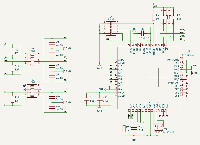
    Many modern power measurement chips (ADE7953, ATM90E32AS), energy meters (iEM3555, MD-P1-3-RC-16), and power analyzers (ABB M4M, PW3390), and DSP processors with integrated digital integrators (ADS131E08, TMS320F280049, MCP3910, STM32G4).

    1. 2. Specialized applications

    Certain motor fault detection or pulse current testing applications focus solely on high-frequency di/dt and can utilize the raw signal directly.

    1. 3. “Self-Integration” Scenarios

    When the pulse width is significantly shorter than the coil’s time constant, the coil itself exhibits approximate integration characteristics. However, this represents a very niche application.

  • What is the difference between low-voltage current transformers and high-voltage current transformers?

    What is the difference between low-voltage current transformers and high-voltage current transformers?


    Current transformer, abbreviated as (CT), is a device used for measuring alternating current. It converts large current into a smaller current through the principle of electromagnetic induction, making it convenient for measurement, protection and control. Low-voltage current transformers and high-voltage current transformers are mainly distinguished based on their working voltage levels. Low-voltage current transformers are typically used in power systems with an alternating voltage of 1000V (1kV) or below. High-voltage current transformers are used in ultra-high voltage power grids ranging from 1kV to 100kV.

    Main differences comparison

    Low Voltage CTHigh Voltage CT
    Voltage LevelIt is typically applicable to low-voltage systems of 1kV and below (such as 0.4kV, 0.66kV).It is suitable for high voltage systems above 1kV (such as 10kV, 35kV, 110kV or even higher).
    Insulation levelThe insulation requirements are relatively low, and dry insulation (such as epoxy resin casting or air insulation) is often used, with a low withstand voltage.High insulation requirements are required, and oil-immersed, SF6 gas insulation, or composite insulation are often used to withstand high voltage and prevent breakdown.
    Structural designIt has a simple structure, small size, and light weight, and is usually a ring or rectangular iron core, making it easy to install.The structure is complex and the volume is large, which may include porcelain sleeves, oil tanks or gas chambers to ensure safe isolation.
    ApplicationIt is widely used in low-voltage distribution cabinets, industrial control systems, metering instruments, and household appliance protection.It is widely used in high-voltage substations, transmission lines, and power plants for measurement, protection relays, and fault monitoring.
    Safety and MaintenanceIt is easy to install and maintain, has low cost, and low risk.It has strict safety requirements, is complex to maintain, requires regular inspection of insulating oil or gas, and is costly.
    Standards and SpecificationsIt complies with standards such as IEC 61869-2, but focuses on low-voltage safety.It complies with standards such as IEC 61869-2, emphasizing high-voltage insulation and shock resistance.


  • What is current transformer ratio?

    What is current transformer ratio?

    The current transformer ratio represents the ratio of primary to secondary current, for example, 500/5, 250/5, or 100/5. A ratio of 500/5 indicates that when the primary current reaches 500A, the secondary current is 5A.

    Standard primary-side rated current ratios include 20, 30, 40, 50, 75, 100, 150, and 2×a/C, with secondary-side rated currents typically being 1A or 5A. The notation 2×a/C signifies a dual-ratio transformer achievable through series (a/c) or parallel (2×a/C) connection of internal components. For metering applications, the primary rated current (I1n) should be greater than or equal to the calculated load current (IC). For instance, a load current of 350A would require a 400/5 current transformer. For protection applications, a larger transformation ratio may be selected to ensure accuracy.

  • Why must a Rogowski coil be used in conjunction with an integrator?

    Why must a Rogowski coil be used in conjunction with an integrator?

    Rogowski coils, also known as hollow coils or flexible current transformers, have gained widespread application in power monitoring, high-frequency pulse current measurement, and high-current protection due to their significant advantages such as non-magnetic saturation, wide measurement range, and easy installation. However, in practical applications, Rogowski coils cannot typically be directly connected to measuring instruments but must be used in conjunction with an integrator.

    1. The Physical Nature of the Rogowski Coil: di/dt Sensor

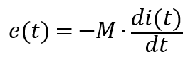
    The operating principle of the Rogowski coil is based on Faraday’s law of electromagnetic induction. When the measured current i(t) passes through the center of the coil, an induced electromotive force e(t) is generated within the coil. Its mathematical expression is:

    Faraday's law of electromagnetic induction

    Here, M represents the mutual inductance coefficient between the coil and the primary conductor.

    From the formula, it can be seen that the output voltage of the Rogowski coil does not directly correspond to the magnitude of the current, but is proportional to the rate of change (derivative) of the current. This means:

    • If the current is a constant direct current, the output of the Rogowski coil is zero.
    • If the current is a sine wave, the output voltage will lead the current by 90° in phase, and its amplitude will increase linearly with frequency.

    Therefore, to reconstruct the true current waveform i(t), the output signal from the coil must undergo mathematical integration processing.

    2. Core Functionality of the Integrator

    The integrator plays a crucial role in the Rogowski coil measurement system, with its functions primarily manifested in the following three aspects:

    1 Waveform Reconstruction (Integration): An electronic integration circuit (typically an active integrator composed of operational amplifiers) converts the di/dt signal into a voltage signal proportional to i(t).
    2 Phase Correction: Compensates for the 90° phase lead generated by the Rogowski coil, ensuring the output signal is in phase with the original current signal. This is critical for power measurements, such as calculating power factor.
    3 Signal Conditioning and Amplification: The raw induced voltage from the current loop is typically very weak (millivolt level). The integrator amplifies it to standard levels and enhances drive capability for long-distance transmission or load driving.

    3. Comparative Analysis of Common Output Types for Integrators

    Depending on the specific requirements of the backend receiving equipment (such as electricity meters, PLCs, oscilloscopes, or relay protection devices), integrators are designed with multiple output formats. The following table provides a detailed comparison of these common output types:


    Output TypeTypical SpecificationsSignal CharacteristicsPrimary ApplicationsAdvantagesDisadvantages
    Instantaneous voltage output333mV AC, 1V ACAC WaveformDigital Energy Meters, Power AnalyzersHigh safety (no secondary open-circuit high voltage), excellent linearityLimited transmission distance, susceptible to electromagnetic interference
    Instantaneous current output1A AC, 5A ACAC WaveformReplacing traditional current transformers (CTs), relay protectionCompatible with legacy equipment, strong drive capability, suitable for remote transmissionHigh power consumption, requiring high-power power supply support
    Standard analog signal4-20mA DC, 0-1V DCDC/Process SignalPLCs, DCS, industrial automation control systemsStrong anti-interference capability (4-20mA), easy system integrationLoss of original waveform information, reflecting only the effective value
    Output without integratorVoltage(di/dt)AC Differential WaveformHigh-frequency transient analysis, data acquisition devices with built-in integration capabilitiesExtremely high bandwidth, no integral drift, fastest responseCannot directly read current values, requiring complex backend processing

    3.1 Instantaneous Voltage Output (333mV / 1V AC)

    This is currently the most prevalent output method for Rogowski coils. 333mV represents the standard low-voltage transformer specification widely adopted in North America and internationally. The primary advantage of this output method is safety: even if the secondary circuit is disconnected, it does not generate lethal high voltages like traditional current transformers. It perfectly preserves current harmonic information, making it ideal for high-precision power quality analysis.

    3.2 Instantaneous Current Output (1A / 5A AC)

    To maintain compatibility with secondary instruments originally designed for traditional core-type CTs, integrators can output 1A or 5A currents. This type of integrator essentially functions as a “voltage-to-current” power amplifier. It resolves the issue of Rogowski coils being unable to directly drive high-impedance loads. However, due to the need to output larger currents, the integrator’s own power consumption and physical size increase significantly.

    3.3 Standard Signal Output (4-20mA / 0-1V DC)

    In industrial automation, users often require only the RMS value of current without needing to inspect waveforms. These integrators incorporate internal RMS-DC conversion circuits that transform complex AC signals into stable DC signals. The 4-20mA current loop output offers exceptional noise immunity, making it ideal for long-distance transmission to PLC or DCS systems.

    3.4 Non-Integrator Output (di/dt)

    In specialized scientific applications, such as lightning current measurement or high-energy physics experiments, users may directly capture the raw di/dt signal from the Rogowski coil. This approach bypasses bandwidth limitations and low-frequency drift inherent to integrators, enabling digital integration via post-processing algorithms to achieve extremely high measurement bandwidths (up to several MHz or higher).

    4. Summary

    The integrator addresses core issues of waveform reconstruction, phase correction, and signal amplification.
    Selecting the appropriate output type depends on your backend equipment:

    •For precision and safety, choose 333mV/1V AC;
    •For compatibility with legacy systems, choose 1A/5A AC;
    • For industrial monitoring, choose 4-20mA DC;
    •When using metering equipment compatible with Rogowski coils or conducting high-frequency research, consider utilizing the direct di/dt output.

    By properly matching the Rogowski coil with the integrator, you can fully leverage its non-saturating, wide-range capabilities to achieve precise control over complex current environments.

  • Phasenwinkelfehler von Stromwandlern: Der unsichtbare Einflussfaktor bei der Energiemessung

    Phasenwinkelfehler von Stromwandlern: Der unsichtbare Einflussfaktor bei der Energiemessung

    In elektrischen Versorgungssystemen ist eine präzise Energiemessung die Grundlage für eine faire Abrechnung, Energieeinsparungen und einen stabilen Systembetrieb.
    Als wichtige Bestandteile von Energieüberwachungssystemen bestimmen Stromwandler (CTs) mit ihrer Genauigkeit unmittelbar die Präzision der Messwerte.
    Neben dem bekannten “Übersetzungsfehler” (Amplitudenfehler) kann jedoch ein häufig übersehener, aber entscheidender Parameter die Genauigkeit der Energiemessung unter bestimmten Bedingungen stark beeinflussen: der Phasenwinkelfehler.

    1. Was ist der Phasenwinkelfehler eines Stromwandlers?

    Um den Phasenwinkelfehler zu verstehen, müssen wir zunächst den Unterschied zwischen dem theoretischen Idealfall und der Praxis betrachten.

    • Idealfall: Ein idealer Stromwandler sollte ein Sekundärstromsignal liefern, das zum Primärstromsignal des Hauptstromkreises genau gegenphasig ist, also einen Phasenunterschied von exakt 180° aufweist.
    • In der Praxis: Bei realen Stromwandlern ist der Sekundärstrom gegenüber dem Primärstrom nicht exakt um 180° phasenverschoben, sondern weist eine kleine Winkelabweichung auf. Der Winkel zwischen dem tatsächlichen Sekundärstromzeiger und dem idealen, zum Primärstrom entgegengesetzten Zeiger wird als Phasenwinkelfehler bezeichnet.

    Gemäß internationalen Normen ist der Phasenwinkelfehler positiv (+), wenn der Sekundärstromzeiger der idealen Lage in der Phase voreilt. Eilt er ihr nach, ist der Phasenwinkelfehler negativ (-).
    Dieser scheinbar unbedeutende Winkel ist für die hochpräzise Energiemessung entscheidend.

    2. Warum weisen Stromwandler eine Phasenverschiebung auf?

    Die Ursache des Phasenwinkelfehlers liegt in den Eigenschaften des physikalischen Aufbaus und des elektromagnetischen Funktionsprinzips des Stromwandlers, insbesondere im Erregerstrom.

    Stromwandler funktionieren ähnlich wie andere Transformatoren: Der durch den Kern fließende Primärstrom erzeugt ein Magnetfeld, das wiederum einen Sekundärstrom induziert.
    Um das erforderliche Magnetfeld im Kern aufzubauen, nimmt der Stromwandler selbst einen Teil der Energie auf. Der dieser Energieaufnahme entsprechende Strom ist der Erregerstrom.

    • Magnetisierungsanteil: Er dient zum Aufbau des Magnetfelds im Kern. Seine Phase eilt der induzierten elektromotorischen Kraft um 90° nach.
    • Eisenverlustanteil: Er gleicht die durch Hysterese und Wirbelströme bei wechselnden Magnetfeldern entstehenden Energieverluste im Kern aus. Er ist mit der induzierten elektromotorischen Kraft in Phase.

    Da der Primärstrom I₁ gleich der Vektorsumme aus dem auf die Primärseite umgerechneten Sekundärstrom I₂ und dem Erregerstrom I₀ ist (I₁ = I₂ + I₀),
    führt der phasenverschobene Erregerstrom I₀ zwangsläufig zu einem Phasenunterschied zwischen I₁ und I₂.
    Dieser Phasenunterschied zeigt sich schließlich als Winkelabweichung im Stromwandler.

    Vereinfacht gesagt ist die Winkelabweichung eine durch den Erregerstrom verursachte “Störung” der Phasenbeziehung zwischen den Strömen.
    Alle Faktoren, die Betrag und Phase des Erregerstroms beeinflussen – etwa die magnetischen Eigenschaften des Kernmaterials, die an die Sekundärseite angeschlossene Bürde und die Höhe des Primärstroms –, wirken sich unmittelbar auf die Winkelabweichung aus.

    3. Wie beeinflusst die Winkelabweichung die Genauigkeit der Überwachung elektrischer Energie?

    Die Formel zur Berechnung der elektrischen Leistung (Wirkleistung) lautet:

    P = U × I × cos(φ), wobei φ der Phasenwinkel zwischen Spannung und Strom und cos(φ) der Leistungsfaktor ist.

    Der Phasenwinkelfehler des Stromwandlers verändert unmittelbar den vom Energiezähler erfassten Phasenwinkel φ und führt dadurch zu Fehlern bei der Leistungsberechnung.

    Zusammenhang der Fehlerfortpflanzung: Der Gesamtfehler der Energiemessung entspricht näherungsweise der Summe aus Spannungsübersetzungsfehler, Stromübersetzungsfehler und Phasenwinkelfehler.
    Eine vereinfachte Formel lautet:

    Fehler der Leistungsmessung ≈ Spannungsübersetzungsfehler + Stromübersetzungsfehler + tan(φ) × Δφ

    Dabei bezeichnet Δφ den von den Messwandlern verursachten Phasenwinkelfehler.

    Wichtigster Einflussfaktor: Leistungsfaktor

    • Hoher Leistungsfaktor (cos(φ) ≈ 1, φ ≈ 0°): tan(φ) ist sehr klein, sodass der Winkelfehler Δφ nur wenig zum Gesamtfehler beiträgt. Der Messfehler wird hauptsächlich durch den “Übersetzungsfehler” (Amplitudenfehler) bestimmt.
    • Niedriger Leistungsfaktor (cos(φ) → 0, φ → ±90°): tan(φ) wird sehr groß. Selbst ein kleiner Phasenwinkelfehler Δφ kann, durch tan(φ) verstärkt, erhebliche Fehler bei der Leistungsmessung verursachen.

    Ein Beispiel: In einem Stromkreis mit extrem niedrigem Leistungsfaktor kann der berechnete Energiewert erheblich vom tatsächlichen Wert abweichen, selbst wenn der Übersetzungsfehler (Amplitudenfehler) des Messwandlers sehr klein ist,
    sofern ein Phasenwinkelfehler vorliegt.

    4. Auswirkungen des Phasenwinkelfehlers

    • Induktive Lasten (z. B. Motoren und Transformatoren mit nacheilendem Leistungsfaktor): Ein positiver Phasenwinkelfehler führt typischerweise dazu, dass der Zähler einen höheren als den tatsächlich verbrauchten Energiewert anzeigt. Dadurch entstehen dem Nutzer unnötige Stromkosten.
    • Kapazitive Lasten (z. B. Kondensatorbänke und übermäßig lange Kabel mit voreilendem Leistungsfaktor): Ein positiver Phasenwinkelfehler führt dazu, dass der Zähler einen niedrigeren als den tatsächlich verbrauchten Energiewert anzeigt. Dadurch entstehen dem Energieversorger Verluste.

    In modernen Industrie- und Gewerbeanlagen ist der Leistungsfaktor durch den weitverbreiteten Einsatz von Frequenzumrichtern, Motoren, LED-Beleuchtung und Schaltnetzteilen zunehmend komplex und häufig ungünstig.
    Vor diesem Hintergrund ist die Phasenwinkelabweichung von Stromwandlern von einer untergeordneten Kenngröße zu einem entscheidenden Faktor dafür geworden, ob ein Energieüberwachungssystem “genau und fair” arbeitet.

  • Gleichtaktdrosseln und Gegentaktinduktivitäten: Unterschiede, Anwendungen und Auswahlkriterien

    Gleichtaktdrosseln und Gegentaktinduktivitäten: Unterschiede, Anwendungen und Auswahlkriterien

     
    Die elektromagnetische Verträglichkeit (EMV) ist ein wichtiger Aspekt bei der Entwicklung moderner elektronischer Geräte. Elektromagnetische Störungen (EMI) beeinträchtigen den normalen Gerätebetrieb und können dazu führen, dass gesetzliche Anforderungen nicht eingehalten werden. Um solche Störungen wirksam zu unterdrücken, setzen Entwickler zahlreiche Filterbauteile ein. Induktivitäten spielen dabei eine zentrale Rolle. Gleichtaktdrosseln und Gegentaktinduktivitäten gehören zu den am häufigsten verwendeten Typen und erfüllen sehr unterschiedliche Aufgaben.


    Obwohl beide zur EMI-Filterung eingesetzt werden, unterscheiden sie sich deutlich hinsichtlich der Störungen, gegen die sie wirken, ihres Aufbaus und ihrer Funktionsweise. Dieser Artikel erläutert die wesentlichen Unterschiede zwischen Gleichtaktdrosseln und Gegentaktinduktivitäten, ihre Anwendungsbereiche und praktische Auswahlkriterien, die Entwicklern bei der Wahl geeigneter Bauteile helfen.

    1. Gleichtaktdrossel

    1.1 Definition und Funktionsweise

    Eine Gleichtaktinduktivität, auch Gleichtaktdrossel genannt, ist ein Filterbauteil, das hauptsächlich Gleichtaktstörungen unterdrückt.


    Eine Gleichtaktstörung (CMN) ist ein Störsignal, das auf zwei Signalleitungen (z. B. den Netzleitungen L und N oder den Datenleitungen D+ und D-) gegenüber Masse oder einer Bezugsebene in gleicher Richtung und Stärke auftritt. Diese Störung entsteht meist durch die Einkopplung äußerer elektromagnetischer Felder oder durch unsymmetrische Schaltungen im Gerät. Sie wird über das Kabel nach außen abgestrahlt oder gelangt über das Kabel in das Gerät.


    Typischerweise besteht eine Gleichtaktinduktivität aus zwei oder mehr Wicklungen, die mit gleicher Windungszahl und Ausrichtung auf denselben hochpermeablen Ferritkern gewickelt sind.


    Ihre Funktionsweise beruht auf der Aufhebung magnetischer Felder und der Wirkung einer hohen Impedanz:


    Bei Gegentaktsignalen (Nutzsignalen): Fließen normale Gegentaktströme (also Ströme gleicher Stärke in entgegengesetzter Richtung auf zwei Leitungen) durch die beiden Wicklungen, entstehen im Kern entgegengesetzte Magnetflüsse, die sich gegenseitig aufheben. Daher ist die Impedanz einer Gleichtaktinduktivität für ein Gegentaktsignal äußerst gering und beeinflusst die Übertragung des Nutzsignals kaum.

    Bei Gleichtaktsignalen (Störungen): Fließen Gleichtaktströme (in gleicher Richtung) durch die beiden Wicklungen, erzeugen sie gleichgerichtete Magnetflüsse im Kern, die sich überlagern. Dadurch weist die Drossel eine hohe Induktivität und damit eine sehr hohe Impedanz für Gleichtaktstörungen auf. So werden diese Störungen unterdrückt und abgeschwächt.


    1.2 Aufbau

    Gleichtaktdrosseln haben üblicherweise vier Anschlussstifte (zwei Eingänge und zwei Ausgänge) und bestehen aus zwei Wicklungen, deren gleichnamige Anschlüsse sich auf derselben Seite des Magnetrings befinden.


    1. Gegentaktinduktivität

    2.1 Definition und Funktionsweise

    Eine Gegentaktinduktivität ist ein herkömmliches induktives Bauteil, das hauptsächlich zur Unterdrückung von Gegentaktstörungen eingesetzt wird.


    Eine Gegentaktstörung (DMN) ist ein Störsignal, das zwischen zwei Signalleitungen in entgegengesetzter Richtung und unterschiedlicher Stärke auftritt. Solche Störungen überlagern das Nutzsignal direkt und entstehen meist durch interne Ursachen wie Schaltvorgänge im Schaltnetzteil, Laständerungen oder eine Fehlanpassung der Signalleitungsimpedanz.


    Eine Gegentaktinduktivität ist ähnlich wie eine gewöhnliche Induktivität aufgebaut und besitzt üblicherweise nur eine Wicklung auf einem Magnetkern.


    Ihre Funktionsweise beruht auf der Selbstinduktion der Spule:


    Bei Gegentaktsignalen (Nutzsignalen und Störungen): Eine Gegentaktinduktivität wirkt Änderungen des Stroms entgegen, der durch sie fließt. Ob es sich um ein normales Gegentaktsignal oder eine Gegentaktstörung handelt: Jeder Strom durch die Induktivität wird von ihrer Induktivität beeinflusst.

    Filterwirkung: Aufgrund ihrer hohen Impedanz bei hohen Frequenzen dämpft eine Gegentaktinduktivität hochfrequente Gegentaktstörungen. Für niederfrequente Nutzsignale (etwa den Gleichstrom einer Stromversorgung oder niederfrequente Wechselstromanteile) bleibt ihre Impedanz gering. So entsteht die Filterwirkung.


    2.2 Aufbau

    Gegentaktinduktivitäten besitzen üblicherweise nur zwei Anschlussstifte und eine Wicklung. In EMI-Filterschaltungen werden sie meist in Reihe in die Stromversorgungs- oder Signalleitung geschaltet.

    1. Vergleich der wesentlichen Unterschiede

    Gleichtaktdrosseln und Gegentaktdrosseln unterscheiden sich vor allem hinsichtlich der Störungsarten, gegen die sie wirken, ihres Aufbaus und ihres Einflusses auf Nutzsignale. Die folgende Tabelle fasst die wichtigsten Unterschiede zusammen:

    MerkmaleGleichtaktdrosselGegentaktinduktivität
    Unterdrückte Störung


    Gleichtaktstörungen (gleichgerichtete Störungen gegenüber Masse)Gleichtaktstörungen (Störungen zwischen Signalleitungen)
    FunktionsweiseDie Überlagerung der Magnetflüsse erzeugt eine hohe Impedanz (für Gleichtakt), während ihre gegenseitige Aufhebung eine geringe Impedanz erzeugt (für Gegentakt).Selbstinduktion erzeugt eine hohe Impedanz (für alle hochfrequenten Ströme).
    AufbauZwei Wicklungen in gleicher Richtung auf demselben MagnetkernEine Wicklung auf einem Magnetkern
    Anzahl der Anschlussstifte4 (zwei Eingänge, zwei Ausgänge)2 (ein Eingang, ein Ausgang)
    Einfluss auf NutzsignaleÄußerst geringe Impedanz und praktisch keine DämpfungEine gewisse Impedanz kann zu einer leichten Dämpfung des Nutzsignals führen.
    EinsatzortTypischerweise an den Ein- oder Ausgängen von Stromversorgungskabeln oder schnellen Signalleitungen zur Filterung abgestrahlter Störungen.Typischerweise in Reihe mit Stromversorgungs- oder Signalleitungen zur Filterung leitungsgebundener Störungen.
    1. Anwendungsbereiche

    4.1 Anwendungsbereiche für Gleichtaktdrosseln

    Da Gleichtaktdrosseln Gleichtaktstörungen wirksam unterdrücken, ohne die Übertragung von Gegentaktsignalen zu beeinträchtigen, werden sie häufig in folgenden Bereichen eingesetzt:


      • Schaltnetzteile (SMPS): In der Eingangsstufe von AC/DC- oder DC/DC-Wandlern unterdrücken sie die durch Schaltvorgänge erzeugten Gleichtaktstörungen und verhindern deren Weiterleitung und Abstrahlung über Stromversorgungsleitungen.
      • Datenkommunikationsschnittstellen: Bei schnellen differenziellen Signalleitungen wie USB, HDMI und Ethernet (RJ45-Steckverbinder) filtern Gleichtaktdrosseln von außen eingekoppelte Gleichtaktstörungen, während die Integrität der Gegentaktsignale erhalten bleibt.
      • Fahrzeugelektronik: Sie werden in Fahrzeugnetzwerken (z. B. CAN und LIN) und Stromversorgungsleitungen eingesetzt, um den komplexen elektromagnetischen Bedingungen standzuhalten.


      4.2 Anwendungen von Gegentaktdrosseln

      Gegentaktdrosseln unterdrücken hauptsächlich Gegentaktstörungen auf Stromversorgungsleitungen. Häufig werden sie zusammen mit Kondensatoren als π- oder L-Filter eingesetzt:


        • Filterung von Stromversorgungsleitungen: An Versorgungseingängen bilden sie zusammen mit X-Kondensatoren Gegentaktfilter, die intern erzeugte leitungsgebundene Gegentaktstörungen dämpfen.
        • Niederfrequente Anwendungen: Sie eignen sich für die Filterung niederfrequenter Stromversorgungen oder für Signalverarbeitungsschaltungen, in denen die Dämpfung hochfrequenter Signale unkritisch ist.
        • Ausgänge von DC/DC-Wandlern: Sie glätten den Ausgangsstrom und unterdrücken den Gegentaktanteil der Schaltwelligkeit.
        1. Auswahlkriterien

        Die richtige Auswahl ist entscheidend für eine wirksame EMI-Filterung. Bei der Wahl von Gleichtakt- und Gegentaktinduktivitäten sind folgende wesentliche Kenngrößen zu berücksichtigen:


        5.1 Auswahlkriterien für Gleichtaktdrosseln

         Nennstrom (I_rated): Die Drossel muss dem maximalen Dauerbetriebsstrom der Schaltung standhalten.

        Gleichtaktimpedanz (Z_CM): Dies ist die wichtigste Kenngröße. Wählen Sie Drosseln, deren Impedanz bei der zu unterdrückenden Störfrequenz (typischerweise einige zehn bis einige hundert MHz) möglichst hoch ist. Eine höhere Impedanz bewirkt eine bessere Unterdrückung.

        Gegentaktimpedanz (Z_DM): Wählen Sie Induktivitäten mit geringer Gegentaktimpedanz, um die Dämpfung von Nutzsignalen zu minimieren.

        Gleichstromwiderstand (DCR): Ein niedriger DCR ist vorzuziehen, um Leistungsverluste und Temperaturanstieg zu verringern.

        Betriebsfrequenzbereich: Wählen Sie Kernmaterial und Wicklungsaufbau entsprechend der Betriebsfrequenz der Schaltung und der Störfrequenz.


        5.2 Wichtige Kriterien bei der Auswahl von Gegentaktinduktivitäten

        Induktivität (L): Bestimmen Sie den Induktivitätswert anhand der erforderlichen Grenzfrequenz und Filtereigenschaften. Eine höhere Induktivität dämpft niederfrequente Störungen besser.

        Nennstrom (I_rated): Wie bei Gleichtaktinduktivitäten muss der Nennstrom mindestens dem maximalen Betriebsstrom der Schaltung entsprechen.

        Sättigungsstrom (I_sat): Überschreitet der Strom einen bestimmten Schwellenwert, sättigt der Kern und die Induktivität fällt stark ab. Damit die Filterwirkung erhalten bleibt, muss der Sättigungsstrom bei der Auswahl über dem Spitzenstrom der Schaltung liegen.

        Gleichstromwiderstand (DCR): Auch hier sollte der DCR möglichst niedrig sein.

        Fazit

        Gleichtaktdrosseln und Gegentaktinduktivitäten sind zwei unverzichtbare Bauteile in EMI-Filterschaltungen. Gleichtaktinduktivitäten unterdrücken dank ihrer besonderen Bauweise mit zwei Wicklungen Gleichtaktstörungen wirksam und erhalten zugleich die Integrität der Nutzsignale. Sie sind eine bevorzugte Wahl, um die Abstrahlung über schnelle Signalleitungen und Stromversorgungsleitungen zu verringern. Gegentaktinduktivitäten dämpfen durch Selbstinduktion Gegentaktstörungen direkt und bilden eine Grundlage für die Filterung leitungsgebundener Störungen auf Stromversorgungsleitungen.


        Das Verständnis ihrer grundlegenden Unterschiede bei den unterdrückten Störungen, im Aufbau und in der Funktionsweise ist die Grundlage für eine geeignete Schaltungsentwicklung und Bauteilauswahl. Erst wenn Störungsart und Schaltungsanforderungen angemessen berücksichtigt werden, lässt sich ein elektronisches System entwickeln, das strenge EMV-Normen erfüllt.

  • Why are the rated secondary currents of current transformers (CTs) equipped with electricity meters almost always 5A (or 1A)?

    Why are the rated secondary currents of current transformers (CTs) equipped with electricity meters almost always 5A (or 1A)?


    In power systems, measuring devices such as electricity meters typically need to be connected to high-voltage or high-current circuits via current transformers (CTs). A common standard is that the interface parameters of electricity meters and the rated secondary current of their matching CTs are almost always 5A (or 1A). This article will delve into the reasons behind this standard and, in conjunction with common parameter markings on electricity meters, explain how to correctly select the matching current transformer.

    1. Interpretation of Current Transformer Parameters

    The current transformer parameters supported by the meter are usually marked on the meter, such as 0.25-5(6)A, 0.015-1.5(6)A, 0.25-5(80)A, 0.25-5(100)A, etc. These parameters identify the operating range and technical requirements when connecting to an external CT. These parameters identify the operating range and technical requirements of the meter when connected to an external CT:
    Take 0.015-1.5(6)A as an example:
    * Starting current (0.015): the minimum current of 15mA that the meter can accurately measure.
    * Basic current Ib(1.5):The rated current value of the energy meter is 1.5A, and the accuracy level of the energy meter can be guaranteed when it works under this current.
    * Maximum current Imax(6): the maximum current at which the meter can be carried safely and continuously without damage, 6 A. This is covered in the IEC/EN 62053 specification for electricity meters.

    2. How to select the correct current transformer (CT) according to the parameters

    Two core principles must be followed in selecting a matching current transformer: secondary current matching and primary current sizing.

    Matching of rated secondary current (key)

    The rated secondary current of the CT must match the basic current Ib of the energy meter.
    – For meters with parameters 0.25-5(6)A, 0.25-5(80)A, 0.25-5(100)A, you need a current transformer with a 5A rated secondary current.
    – For energy meters with parameters 0.015-1.5(6)A (used in specific scenarios although the base current is not 5A/1A standard), you need to equip a CT with a rated secondary current of 1.5A (these are less common and usually follow the 5A or 1A standard).

    Selection of Rated Primary Current and Variable Ratio

    The rated primary current of the CT (which determines the variable ratio, e.g., 100/5A, 500/5A, 100/1A) should be selected in accordance with the load current of the actual primary circuit. The selection principle is to make the actual load current of normal operation close to the rated primary current of the CT. According to IEC/EN 61869 standard, 1.2 times of the rated primary current is also in line with the nominal accuracy of the product, so the best measurement accuracy can be ensured.
    Therefore, for energy meters with parameters of 0.015-1.5(6)A, the best match is a current transformer (CT) with a secondary rated output of 1A.
    If you are interested in the measurement of small currents and do not have high requirements for measurement accuracy and range, you can also choose a current transformer (CT) with a secondary rated output of 100mA.

    3. Why has 5A (or 1A) become the industry standard?

    Returning to the question at the heart of the article, why has the industry generally adopted 5A or 1A as the standard secondary current for CTs? The reason is a combination of performance, standardization, and safety:
    Performance Requirements and Historical Reasons
    Early electromechanical energy meters and protective relays required a certain amount of physical energy (power) to actuate the mechanical components. 5A current provided a strong enough signal and power to ensure reliable and accurate operation of these devices. Current signals in the milliamp range are too weak, susceptible to interference and unable to drive older devices.
    Standardization and Global Interchangeability
    5A is established as the global standard for the power industry, ensuring that devices from different manufacturers and countries are easily compatible and interchangeable, greatly simplifying system design, manufacturing and maintenance.
    Balancing Safety and Economy
    The core safety objective of the CT is to isolate the high voltage high current circuits from the low voltage measurement circuits. 5A’s relatively low secondary current reduces operational risk. At the same time, the 5A strikes a good balance between cabling costs, wire cross-section requirements and power loss. Where long wiring distances are required, the 1A standard is used to further reduce line losses (1A losses are only 4% of 5A).
    In summary, the selection of 5A (or 1A) as the standard secondary current for CTs is the result of engineering practices that optimize performance, cost, historical compatibility and operational reliability.

  • Vergleich: Rogowski-Spulen und Stromwandler

    Vergleich: Rogowski-Spulen und Stromwandler

     
    Die Rogowski-Spulen (RC) und Stromwandler (CTs) sind zwei grundlegende Technologien zur Messung von Wechselstrom. Beide beruhen auf elektromagnetischer Induktion. Sie unterscheiden sich jedoch grundlegend im Aufbau: Das Vorhandensein oder Fehlen eines Magnetkerns wirkt sich erheblich auf Leistung, Einsatzgebiete und Sicherheit aus. Stromwandler besitzen einen Kern und eignen sich besonders für hochpräzise Messungen bei niedrigen Frequenzen und im stationären Betrieb. Rogowski-Spulen haben keinen Kern. Sie bieten größere Flexibilität, einen breiteren Dynamikbereich und sind unempfindlich gegen Kernsättigung. Dadurch eignen sie sich besonders für hohe Ströme, hohe Frequenzen und transiente Vorgänge.

    I. Grundlegende Unterschiede: Funktionsprinzip und Aufbau

    Der Kernaufbau ist das wichtigste Unterscheidungsmerkmal der beiden Technologien.


    MerkmalRogowski-Spule (RC)Stromwandler (CT)
    KernaufbauKernlos (Luftkern).Eisenkern (schwerer Magnetkern).
    FunktionsprinzipBasiert auf dem Faradayschen Induktionsgesetz. Erzeugt eine Spannung, die proportional zur Änderungsrate des Primärstroms (di/dt) ist.Basiert auf elektromagnetischer Induktion. Wandelt den Primärstrom durch magnetische Kopplung über den Kern in einen Sekundärstrom um.
    AusgangssignalSchwaches Spannungssignal (di/dt).Stromsignal (sekundärseitig üblicherweise 5 A oder 1 A).
    SignalverarbeitungBenötigt eine externe Integratorschaltung, um das abgeleitete Spannungssignal wieder in ein zum Strom proportionales Signal umzuwandeln.Der Ausgangsstrom wird üblicherweise direkt gemessen oder über einen Bürdenwiderstand in eine Spannung umgewandelt.


    II. Vergleich von Leistung und Sicherheit

    Der kernlose Aufbau der Rogowski-Spule bietet deutliche Vorteile beim Dynamikbereich und bei der Sicherheit. Der Eisenkern des Stromwandlers ermöglicht dagegen einen einfachen Aufbau und eine hohe Genauigkeit unter Nennbedingungen.


    EigenschaftRogowski-Spule (RC)Stromwandler (CT)
    KernsättigungKeine. Auch bei extrem hohen Strömen tritt keine magnetische Sättigung auf.Bei Strömen oberhalb des Nennwerts kann der Kern sättigen. Dies führt zu einem nichtlinearen Verhalten und fehlerhaften Messungen.
    MessbereichSehr breit. Eine einzelne Einheit kann Ströme von wenigen Ampere bis zu mehreren Tausend Ampere (z. B. 10 kA) messen.Enger. Durch Kerngröße und Sättigungsgrenze begrenzt. Für unterschiedliche Strombereiche sind verschiedene Stromwandler erforderlich.
    FrequenzverhaltenHervorragende, große Bandbreite. Sehr gutes Verhalten bei hochfrequenten und transienten Strömen (z. B. Motoranlaufströmen und Stromimpulsen).Begrenzt. Das Frequenzverhalten wird durch das Kernmaterial eingeschränkt. Am besten für Netzfrequenzen (50/60 Hz) geeignet.
    LinearitätHervorragend. Über den gesamten breiten Messbereich bleibt das Verhalten linear.Hohe Genauigkeit bei Nennstrom und Nennfrequenz; bei Sättigung nimmt die Linearität jedoch erheblich ab.
    Sicherheit (offener Sekundärkreis)Grundsätzlich sicher. Das Ausgangssignal ist eine niedrige Spannung; bei offenem Sekundärkreis entsteht keine gefährliche Hochspannung.Gefährlich. Wird der Sekundärkreis bei fließendem Strom geöffnet, können extrem hohe, lebensgefährliche Spannungen entstehen.
    BauformFlexibel und leicht (z. B. etwa ein halbes Pfund bei einer Einheit für 5.000 A).Starr, schwer und sperrig (z. B. bis zu 65 Pfund bei einem vergleichbaren Messbereich).
    InstallationEinfach. Die flexible Bauform zum Umlegen erleichtert die Installation an Sammelschienen oder unregelmäßig geformten Leitern, besonders bei wenig Platz.Schwierig. Die starre Bauform erfordert bei großen oder unregelmäßig geformten Leitern häufig eine vollständige Stromabschaltung und Sonderanfertigungen [3].
    Komplexität/KostenDie Verwendung ist wegen des erforderlichen externen oder integrierten Integrators aufwendiger. Kann teurer sein als ein einfacher Stromwandler.Einfacher zu verwenden (direkter Stromausgang). Für Standardanwendungen meist kostengünstiger.


    III. Einsatzgebiete

    Die Wahl zwischen einer Rogowski-Spule und einem Stromwandler hängt stark von den Anforderungen der jeweiligen Anwendung ab.


    TechnologieIdeale AnwendungenWeniger geeignete Anwendungen
    Rogowski-Spule– Überwachung hoher Ströme (z. B. bis zu 5.000 A und darüber).– Gleichstrommessung (Rogowski-Spulen messen nur Wechselstrom bzw. Stromänderungen).
    – Analyse hochfrequenter und transienter Vorgänge (z. B. in der Leistungselektronik sowie von Motoranlauf- und Fehlerströmen).– Anwendungen, bei denen Kosten oder Aufwand für den Integrator zu hoch sind.
    – Nachrüstung oder Installation bei unregelmäßig geformten Leitern oder begrenztem Platzangebot.– Standardmäßige Energiezählung, wenn ausschließlich hochpräzise Messungen bei niedrigen Frequenzen erforderlich sind.
    Stromwandler– Standardmäßige Energiezählung und Abrechnung (hohe Genauigkeit bei 50/60 Hz).– Messung hoher Ströme, bei der Sättigungsgefahr besteht.
    – Relaisschutz und industrielle Überwachung bei Netzfrequenzen.– Analyse hochfrequenter oder transienter Ströme.
    – Anwendungen, bei denen Einfachheit und geringe Kosten Vorrang haben.– Installationen mit unregelmäßig geformten Sammelschienen oder sehr wenig Platz.


    Fazit

    Rogowski-Spulen und Stromwandler ergänzen einander. Der Stromwandler bleibt die bewährte Lösung für die herkömmliche, hochpräzise Überwachung und den Schutz bei Netzfrequenzen und stationären Betriebsbedingungen. Die kernlose Rogowski-Spule bietet eine moderne, flexible und sicherere Lösung für anspruchsvolle Anwendungen mit hohen Strömen, großen Dynamikbereichen und hochfrequenten Transienten, insbesondere bei der Analyse der Netzqualität und bei Prüfungen in der Leistungselektronik.

  • Warum 4-20-mA-Stromsignale verwenden?

    Warum 4-20-mA-Stromsignale verwenden

    In industriellen Mess- und Regelsystemen wandeln Strommessumformer und Spannungsmessumformer analoge Signale in standardisierte elektrische Signale um. Diese werden über große Entfernungen an Leitwarten übertragen, wo sie überwacht, aufgezeichnet und zur Regelung genutzt werden. Einheitliche Standardsignale sind entscheidend für die Zusammenarbeit verschiedener Geräte und die Stabilität des Systems. Die Internationale Elektrotechnische Kommission (IEC) hat 4-20 mA Gleichstrom und 1-5 V Gleichspannung (durch Umwandlung mittels Widerstand) als Standards für analoge Signale in Prozessleitsystemen festgelegt.

    1. Vorteile von Stromsignalen

    Bei der Übertragung über große Entfernungen bieten Stromsignale erhebliche Vorteile gegenüber Spannungssignalen. In industriellen Umgebungen treten häufig starke elektromagnetische Störungen auf, die Spannungssignale leicht verfälschen. Zudem verursacht der Leitungswiderstand bei längeren Übertragungsstrecken Spannungsabfälle. Dadurch werden Spannungssignale abgeschwächt und Messfehler entstehen.

    Die Vorteile von Stromsignalen zeigen sich vor allem in folgenden Punkten:

    • Hohe Störfestigkeit: Störspannungen in industriellen Umgebungen können mehrere Volt erreichen. Ihre Störleistung ist jedoch gering, sodass sie typischerweise Störströme unterhalb des nA-Bereichs erzeugen. Stromsignale werden vom Leitungswiderstand weniger beeinflusst, sind weniger anfällig für Abschwächung und ermöglichen eine zuverlässige Datenübertragung auch bei starken elektrischen Störungen.
    • Große Übertragungsentfernung: Stromquellen haben einen unendlich hohen Innenwiderstand. Daher beeinträchtigt der in Reihe liegende Leitungswiderstand im Stromkreis die Genauigkeit nicht. Solange der Übertragungsstromkreis unverzweigt bleibt, ist der Strom unabhängig von der Leitungslänge überall gleich. So ist eine präzise Übertragung über Hunderte von Metern oder mehr mit herkömmlichen verdrillten Leitungen möglich.
    • Weniger Verkabelung: Bei der Übertragung eines Zweileiter-4-20-mA-Signals dienen dieselben Leitungen sowohl der Stromversorgung als auch der Signalübertragung. Das verringert den Kabelbedarf und damit Kosten und Aufwand für die Verdrahtung.

    2. Warum ein 4-20-mA-Gleichstromsignal?

    Das 4-20-mA-Gleichstromsignal ist das am weitesten verbreitete analoge Standardsignal in industriellen Anwendungen. Die Wahl dieses Signalbereichs beruht auf verschiedenen technischen und sicherheitsbezogenen Überlegungen.

    2.1 Warum 4 mA als Anfangswert gewählt wurden („lebender Nullpunkt“)

    Dass das 4-20-mA-Signal bei 4 mA statt bei 0 mA beginnt, ist eines seiner wichtigsten Merkmale. Dies wird als „lebender Nullpunkt“ bezeichnet.
    • Fehlerdiagnose: Zeigt das Signal 0 mA an, weist dies eindeutig auf eine Leitungsunterbrechung (einen offenen Stromkreis) oder einen Geräteausfall hin und nicht auf einen Messwert von null. So lassen sich Fehler einfach erkennen, ohne einen Nullwert mit einer unterbrochenen Leitung zu verwechseln.
    • Stromversorgung des Sensors: Bei Zweileiter-Messumformern liefern die 4 mA den Mindeststrom, den die Sensoren für ihren Betrieb benötigen. Zusätzliche Versorgungsleitungen sind dadurch nicht erforderlich, was die Verdrahtung vereinfacht.

    2.2 Warum 20 mA als Endwert gewählt wurden

    Die Wahl von 20 mA als Signalwert bei Vollausschlag beruht ebenfalls auf Sicherheits- und Praxiserwägungen.

    • Sicherheit: Die bei einem Stromfluss von 20 mA entstehende Funkenenergie reicht nicht aus, um Gas zu entzünden. Damit werden die Anforderungen an die Eigensicherheit beim Explosionsschutz erfüllt – ein entscheidender Aspekt in industriellen Umgebungen mit Brand- und Explosionsgefahr.
    • Stromverbrauch und Kosten: 20 mA sind ein vergleichsweise niedriger Stromwert, der bei ausreichender Signalqualität und Ansprechgeschwindigkeit dazu beiträgt, den Stromverbrauch und die Gerätekosten zu senken.

    Fazit

    Zusammenfassend hat sich das 4-20-mA-Gleichstromsignal aufgrund seiner hohen Störfestigkeit, seiner Eignung für große Übertragungsentfernungen, der Fehlererkennung durch den „lebenden Nullpunkt“ und seiner Eigensicherheit als der am weitesten verbreitete Standard in der industriellen Automatisierung und Prozessregelung etabliert. Es überträgt Messdaten zuverlässig, senkt zugleich die Verdrahtungskosten und erhöht die Zuverlässigkeit des Systems.

  • Wie verwendet man einen bidirektionalen Stromsensor zur Messung?

    Wie verwendet man einen bidirektionalen Stromsensor zur Messung?


    1. Ausgangssignal interpretieren

    Die Stromsensoren der HAS-Serie zeigen Stärke und Richtung des gemessenen Stroms über ihre Ausgangsspannung an. Ihr wesentliches Merkmal ist ein Mittelpunkt des Ausgangssignals bei 2,5 V. Je nach Richtung und Stärke des Stroms weicht die Spannung von diesem Wert ab. So kann der Sensor Strom in beide Richtungen messen.

    2. Bedeutung des Ausgangssignals von 2,5 V ± 0,625 V

    Beim Stromsensor HAS14Z liegt die Ausgangsspannung bei 2,5 V ± 0,625 V. Das bedeutet:

    • Nullstrom (0 A): Fließt kein Strom durch den Sensor, beträgt die Ausgangsspannung 2,5 V.
    • Strom in Vorwärtsrichtung: Die Ausgangsspannung steigt von 2,5 V auf maximal 2,5 V + 0,625 V = 3,125 V.
    • Strom in Rückwärtsrichtung: Die Ausgangsspannung sinkt von 2,5 V auf mindestens 2,5 V – 0,625 V = 1,875 V.

    Der Bereich von 2,5 V ± 0,625 V entspricht üblicherweise dem Nennmessstrombereich des Sensors. Der Nennstrom beträgt beispielsweise beim HAS2009 ±20 A und beim HAS4009 ±100 A.

    3. Stromberechnung

    Anhand der Nennempfindlichkeit (SN) des Sensors lässt sich das erfasste Spannungssignal in den tatsächlichen Stromwert umrechnen. Die Formel lautet:
    IP = (Vout – 2,5 V)/SN

    Dabei gilt:

    • IP ist der gemessene Strom (Einheit: A)
    • Vout ist die vom Sensor ausgegebene Spannung (Einheit: V)
    • 2,5 V ist die Referenzspannung bei Nullstrom
    • SN ist die Nennempfindlichkeit des Sensors (Einheit: V/A oder mV/A).

    Beispiel:

    Angenommen, es wird der Stromsensor HAS14Z verwendet (SN = 104,2 mV/A oder 0,1042 V/A).

    • Wenn für Vout 2,8 V gemessen werden: IP = (2,8 V – 2,5 V) / 0,1042 V/A ≈ 2,88 A (Strom in Vorwärtsrichtung)
    • Wenn für Vout 2,2 V gemessen werden: IP = (2,2 V – 2,5 V) / 0,1042 V/A ≈ -2,88 A (Strom in Rückwärtsrichtung)

    4. Sensoranschlüsse und Verdrahtung

    Die Stromsensoren der HAS-Serie haben üblicherweise folgende Anschlüsse:

    • VCC (+5 V): Positiver Anschluss der Sensorversorgung; mit einer stabilen 5-V-Gleichspannungsversorgung verbinden.
    • GND: Die Versorgungs- und Signalmasse des Sensors müssen mit der Masse des Steuerungssystems verbunden sein.
    • OUT (Vout): Spannungsausgang des Sensors zur Erfassung des Stromsignals.

    Typical wiring diagram (taking microcontrollers as an example) :
     bidirectional current sensor for measurement

    Hinweise zur Verdrahtung

    1). Spannungsversorgung: Versorgen Sie den Sensor mit stabilen 5 V. Die Qualität der Spannungsversorgung wirkt sich unmittelbar auf die Messgenauigkeit aus.
    2). Gemeinsame Masse: Sensor und Mikrocontroller müssen dieselbe Masse verwenden, um Messfehler durch Unterschiede im Massepotenzial zu vermeiden.
    3). Verdrahtung: Führen Sie die zu messende Leitung korrekt durch die Messöffnung des Sensors und positionieren Sie sie möglichst mittig, um die beste Messqualität zu erzielen.

    5. Schritte zur Signalerfassung

    Das Ausgangssignal des Stromsensors von 2,5 V ± 0,625 V wird hauptsächlich mit einem Analog-Digital-Wandler (ADC) erfasst. Die einzelnen Schritte sind:
    1). ADC konfigurieren:

    • ADC-Anschluss auswählen: Verbinden Sie den OUT-Anschluss des Sensors mit einem ADC-Eingang des Mikrocontrollers.
    • Referenzspannung einstellen: Stellen Sie die ADC-Referenzspannung auf 5 V ein (wenn der Ausgangsbereich des Sensors 0,25 V bis 4,75 V beträgt), oder wählen Sie eine für den tatsächlichen Aufbau geeignete Referenzspannung. Der ADC muss den gesamten Ausgangsbereich des Sensors erfassen können.
    • Auflösung und Abtastrate einstellen: Wählen Sie ADC-Auflösung (z. B. 10 oder 12 Bit) und Abtastrate entsprechend den Anforderungen der Anwendung. Eine höhere Auflösung ermöglicht genauere Messungen; eine höhere Abtastrate eignet sich für schnell veränderliche Ströme.

    2). ADC-Wert auslesen:

    • Lesen Sie die Digitalwerte des ADC-Eingangs regelmäßig per Mikrocontroller-Programm aus.

    3). ADC-Wert in Spannung umrechnen:

    • Rechnen Sie den ausgelesenen Digitalwert in die tatsächliche Spannung Vout um. Bei einem 10-Bit-ADC (0–1023) mit 5 V Referenzspannung lautet die Formel beispielsweise: Vout = (ADC_Value / 1024.0) * 5.0 (Einheit: V)

    4). Tatsächlichen Strom berechnen

    • Rechnen Sie die Spannung Vout mit folgender Formel in den tatsächlichen Strom IP um: IP = (Vout – 2,5 V)/SN. Dabei ist SN die Nennempfindlichkeit des Sensors (Einheit: V/A). Beim HAS14Z beträgt SN beispielsweise 0,1042 V/A.

    Beispielrechnung
    Angenommen, es wird der Stromsensor HAS14Z verwendet (SN = 0,1042 V/A).

    • Wenn der ADC für Vout eine Ausgangsspannung von 2,8 V misst: IP = (2,8 V – 2,5 V) / 0,1042 V/A ≈ 2,88 A (Strom in Vorwärtsrichtung)
    • Wenn der ADC für Vout eine Ausgangsspannung von 2,2 V misst: IP = (2,2 V – 2,5 V) / 0,1042 V/A ≈ -2,88 A (Strom in Rückwärtsrichtung)

    Mit diesen Schritten können Sie Stärke und Richtung des gemessenen Stroms genau erfassen und berechnen.

    6. Anwendungsbereiche

    Die Stromsensoren der HAS-Serie mit geschlossenem Regelkreis werden dank ihrer bidirektionalen Strommessung und ihres Spannungsausgangs in vielen Bereichen eingesetzt:

    • Motorsteuerung: Ermöglicht eine präzise Drehzahl- und Drehmomentregelung bei Elektrofahrzeugen, Industrierobotern und anderen Geräten.
    • Batteriemanagementsystem (BMS): Überwacht den Lade- und Entladezustand der Batterie, um ihre Lebensdauer und Effizienz zu optimieren.
    • Leistungsmanagement: Regelt den Leistungsfluss präzise, etwa in unterbrechungsfreien Stromversorgungen (UPS), Schaltnetzteilen (SMPS) und Solarwechselrichtern.
    Erneuerbare-Energien-Systeme: Überwachen den Strom an den Verbindungspunkten zwischen Energiespeichern und Stromnetz, um die Energieumwandlung zu optimieren.
    • Industrieautomatisierung: Liefert Stromdaten in Echtzeit für Prozesssteuerung, Fehlerdiagnose und Schutzfunktionen.


  • What is the difference between current transformer, voltage transformer and Control/Safety Isolation Transformer?

    What is the difference between current transformer, voltage transformer and Control/Safety Isolation Transformer?


    Current transformers (CTs), voltage transformers (VTs, also known as potential transformers (PTs), and power transformers all operate based on the principle of electromagnetic induction, but they differ significantly in their design, purpose, and operating characteristics. Simply put, CTs and VTs are instrument transformers, primarily used to measure and protect current or voltage in power systems, while power transformers are power transformers, primarily used for voltage conversion in power transmission and distribution. Below, I will compare them from multiple perspectives.

    1. Basic Definition and Principle

    • Current Transformer (CT): Used to convert high-voltage, high-current to low-voltage, low-current (typically 1A or 5A) for instrument measurement or relay protection. Its operating principle is that the primary winding is connected in series in the circuit, and the secondary winding outputs a signal proportional to the primary current.
    • Voltage Transformer (VT): Used to convert high-voltage, high-current to low-voltage (typically 100V or 110V) for voltage measurement and protection. The primary winding is connected in parallel in the circuit, and the secondary output is proportional to the primary voltage.
    • Control/Safety Isolation Transformer: Used to change voltage levels (e.g., step up or down) in power systems to achieve efficient power transmission and distribution. It is not used for measurement but directly supplies power to the load.

    2. Key Differences Comparison

    The following table summarizes the key differences between the three types of transformers:

    Current Transformer (CT)Voltage Transformer (VT)Control/Safety Isolation Transformer
     ApplicationsMeasure and monitor current and protect equipment (such as relays).Measure and monitor voltage and protect equipment.Provide electrical isolation and voltage conversion for control circuits and safe power supply (such as preventing electric shock and powering low-voltage equipment).
    Working ModeWhen the primary is connected in series with the load circuit, the secondary must be short-circuited (or connected to a low-impedance load) to avoid dangerous high voltages.When the primary is connected in parallel, the secondary is open-circuited or connected to a high-impedance load (such as a meter).The primary and secondary terminals are connected to the power supply and load as required for power transmission and have no measurement function.
    Transformation ratio characteristicsCurrent step-down ratio (high current → low current, e.g., 1000A:5A), low secondary voltage.Voltage step-down ratio (high voltage → low voltage, e.g., 1kV:10V), high secondary impedance.Voltage step-down ratio (e.g. 220V:24V), with emphasis on isolation and power transfer.
    Design FeaturesFewer primary turns, more secondary turns; high precision, low saturation; small capacity (several VA).Similar to a small transformer, high precision; small capacity (several VA to tens of VA).Dual-winding isolation design with shielding for enhanced safety; low-voltage PCB or chassis-mountable; high efficiency, suitable for intermittent or continuous loads; large capacity (several VA to several kilovolts).
    Load requirementsThe secondary must be short-circuited or low-impedance to avoid dangerously high voltages.The secondary can be left open for high-impedance loads (such as instruments).When connecting the secondary to an actual load (such as a control device), it can be left open, but this is not recommended.
    Accuracy and ErrorEmphasizes current measurement accuracy (error <1%).Emphasizes voltage measurement accuracy (error <0.5%).Emphasis is placed on isolation and efficiency (>65%), not measurement accuracy; voltage regulation is low.
    Application ScenarioPower metering, protection systems, ammeters.Voltmeters, power meters, protection relays.Industrial automation, machine tool controls, medical equipment, security lighting, PCB power modules.


  • Anschluss eines Stromwandlers an den Atmel-M90E32AS-Chip

    Anschluss eines Stromwandlers an den Atmel-M90E32AS-Chip


    Einführung

    In modernen Energiezählsystemen ist eine genaue Strommessung entscheidend. Der Atmel M90E32AS ist ein leistungsfähiger Mehrphasen-Energiezähler-IC mit großem Dynamikbereich, der in verschiedenen Energiezählern und Geräten zur Leistungsüberwachung eingesetzt wird. Stromwandler (CTs) spielen eine unverzichtbare Rolle dabei, Signale aus Stromkreisen mit hoher Spannung und hohen Strömen sicher und präzise zur Verarbeitung an den M90E32AS zu übertragen. Dieser Artikel erläutert die Funktionsweise von Stromwandlern und ihren korrekten Anschluss an den M90E32AS für eine zuverlässige Strommessung.

    Überblick über den Atmel-M90E32AS-Chip

    Der Atmel M90E32AS ist ein leistungsfähiger integrierter Schaltkreis für die mehrphasige Energiemessung. Er enthält sechs unabhängige Sigma-Delta-AD-Wandler zweiter Ordnung, die dreiphasige Spannungs- und Stromsignale gleichzeitig verarbeiten können. Der interne digitale Signalprozessor (DSP) des Chips führt komplexe Berechnungen mit den von den AD-Wandlern erfassten Daten durch und ermittelt wichtige Energieparameter wie Wirkleistung, Blindleistung, Scheinleistung, Leistungsfaktor, Frequenz sowie die Effektivwerte (RMS) von Spannung und Strom. Der M90E32AS unterstützt die Stromerfassung über einen Stromwandler (CT) oder eine Rogowski-Spule und die Spannungserfassung über ein Widerstandsteilernetzwerk.

    Stromeingangskanal

    Der M90E32AS-Chip besitzt drei Paare differenzieller Stromeingangsanschlüsse: I1P/I1N, I2P/I2N und I3P/I3N. Sie dienen der Messung des dreiphasigen Stroms. Diese Anschlüsse sind die Eingänge der analogen AD-Wandlerkanäle. Durch die flexible Zuordnung der Kanäle lassen sie sich an unterschiedliche Konfigurationen dreiphasiger Systeme anpassen, etwa an Drei- und Vierleitersysteme.

    Interner AD-Wandler und Abtastung

    Der AD-Wandler im Chip wandelt das analoge Stromsignal in ein digitales Signal um. Der M90E32AS bietet einen großen Dynamikbereich und eine hohe Genauigkeit, sodass über einen breiten Strombereich präzise Messungen möglich sind. Laut Datenblatt erfolgt die Stromerfassung über einen Stromwandler (CT) oder eine Rogowski-Spule (di/dt-Spule) [1]. Der externe Sensor wandelt das Stromsignal somit in ein für den M90E32AS geeignetes Spannungssignal um.

    Signalverarbeitung und Kalibrierung

    Der DSP des M90E32AS berechnet nicht nur Energieparameter, sondern unterstützt auch eine Verstärkungs- und Phasenwinkelkompensation, um Fehler durch externe Sensoren und Schaltungen zu korrigieren. Dies ist entscheidend für die Genauigkeit des gesamten Messsystems. Der Chip bietet außerdem programmierbare Schwellwerte für den Anlauf und die Leerlaufleistung sowie die Überwachung transienter Strom- und Spannungssignale. Dank dieser Funktionen kann der M90E32AS auch unter komplexen Netzbedingungen stabil und zuverlässig arbeiten.

    Funktionsprinzip des Stromwandlers (CT)

    Ein Stromwandler (CT) ist ein spezieller Transformator, der hohe Ströme für Mess-, Schutz- und Steuerungszwecke proportional in kleinere Ströme umwandelt. Seine Hauptfunktionen sind die galvanische Trennung und die Skalierung des Stroms. Das Funktionsprinzip eines Stromwandlers beruht auf dem Gesetz der elektromagnetischen Induktion: Fließt Strom durch die Primärwicklung (gewöhnlich der Leiter, der durch die Mitte des Stromwandlers verläuft), erzeugt er einen magnetischen Fluss im Kern. Dieser Fluss induziert in der Sekundärwicklung eine elektromotorische Kraft, wodurch ein Sekundärstrom entsteht.

    Wichtige Merkmale

    Übersetzungsverhältnis:

    Das Übersetzungsverhältnis eines Stromwandlers ist das Verhältnis seines primärseitigen Nennstroms zum sekundärseitigen Nennstrom, beispielsweise 100 A/5 A oder 100 A/0,1 A. Das bedeutet: Fließen primärseitig 100 A, beträgt der sekundärseitige Ausgangsstrom 5 A beziehungsweise 0,1 A. Für Energiezähler werden typischerweise Stromwandler mit einem Sekundärstrom im Milliamperebereich oder darunter gewählt, damit ein direkter Anschluss an den Stromeingang des Messchips möglich ist.

    Genauigkeitsklasse:

    Die Genauigkeitsklasse eines Stromwandlers gibt seinen Messfehler innerhalb des Nennstrombereichs an. Beispielsweise bedeutet ein Stromwandler der Klasse 0,2S innerhalb eines bestimmten Strombereichs einen Fehler von höchstens ±0,2 %. Dies ist für die hochpräzise Energiemessung entscheidend.

    Bürde:

    Die Bürde eines Stromwandlers bezeichnet die Impedanz des Messinstruments oder Geräts, das an seine Sekundärseite angeschlossen ist. Der Sekundärkreis eines Stromwandlers muss stets geschlossen sein. Andernfalls kann bei offenem Stromkreis an der Sekundärseite eine hohe Spannung entstehen, die den Stromwandler beschädigen oder Personen gefährden kann. Isolation: Stromwandler sorgen für eine galvanische Trennung zwischen dem primärseitigen Hochspannungsstromkreis und dem sekundärseitigen Niederspannungsmesskreis und erhöhen so die Sicherheit und Zuverlässigkeit des Systems.

    Anwendungen in der Energiemessung

    Bei der Energiemessung werden Stromwandler häufig verwendet, um hohe Ströme im Hauptstromkreis zu messen. Sie wandeln das Signal des hohen Stroms im Hauptstromkreis in ein schwächeres Strom- oder Spannungssignal um, das der Messchip verarbeiten kann. Das schützt den Messchip vor der direkten Einwirkung hoher Spannungen und Ströme und macht die Auslegung des Messsystems flexibler und sicherer.

    Anschluss von Stromwandlern an den M90E32AS-Chip

    Beim Anschluss von Stromwandlern an den Atmel-M90E32AS-Chip muss die Signalaufbereitung sorgfältig ausgelegt werden, um Messgenauigkeit und Schutz des Chips zu gewährleisten. Die Stromeingangsanschlüsse des M90E32AS-Chips (I1P/I1N, I2P/I2N und I3P/I3N) sind differenzielle Eingänge. Sie messen die Spannungsdifferenz zwischen den beiden Anschlüssen. Daher muss der Ausgangsstrom des Stromwandlers üblicherweise über einen Messwiderstand in ein Spannungssignal umgewandelt werden, bevor es an die differenziellen Eingänge des Chips gelangt.

    Typische Anschlussschaltung

    Sehen wir uns den Anschluss eines Stromwandlers (CT) an. Üblicherweise wird seine Sekundärseite an einen niederohmigen Shunt-Widerstand angeschlossen. Wenn Strom durch den Shunt-Widerstand fließt, entsteht an ihm ein zum Strom proportionaler Spannungsabfall. Dieser Spannungsabfall dient als Eingangssignal für den AD-Wandler des M90E32AS-Chips.

    Bei einer einphasigen Strommessung wird der Sekundärausgang des Stromwandlers an den Shunt-Widerstand angeschlossen, der wiederum mit den Anschlüssen I_P und I_N des M90E32AS-Chips verbunden ist. Um die Messgenauigkeit zu verbessern und Gleichtaktstörungen zu unterdrücken, wird üblicherweise ein Kondensator parallel zum Shunt-Widerstand geschaltet, sodass ein RC-Filternetzwerk entsteht. Darüber hinaus kann ein Spannungsteilernetzwerk oder eine Vorspannungsschaltung erforderlich sein, um eine geeignete Vorspannung bereitzustellen und sicherzustellen, dass der AD-Wandlereingang innerhalb des Betriebsbereichs des M90E32AS liegt.

    Connection between current transformer and Atmel M90E32AS chip

  • Why vacuum molded PCB Transformers is Important

    Why vacuum molded PCB Transformers is Important


    Potting hazards:

    Potential for cavitation, leading to partial discharge, hot spots, and thermal cycling cracks
    Service life may be reduced by 40–60%

    Advantages of vacuum potting:

    Evacuates air at ≤5 mbar
    Injects UL94V-0 epoxy resin and cures in a moisture-free environment
    Significantly improves insulation performance and thermal stability

    Actual Results and Test Data

    A vacuum-potted medical device transformer passed a 50,000-hour accelerated aging test.
    A non-vacuum-potted device failed after 18,000 hours.

    Ability to cope with extreme environments

    StressorConsequenceVacuum Molded Benefit
    Vibration (5–2000Hz)Wire fatigueDampens resonance 300% better
    Thermal shock (-40~125°C)Solder joint cracksCTE-matched resin absorption
    Humidity (85% RH)Corrosion trackingZero permeability barrier


    Recommendations for verifying potting quality

    –Don’t rely solely on the datasheet, request:
    –X-ray scan showing void distribution
    –Cross-section report measuring bubble size
    –Thermal shock test (-55°C to +150°C, 500 cycles)
    –Partial discharge test <5 pC (at 2x the operating voltage)


    YHDC’s PCB transformers utilize vacuum forming technology, resulting in extremely high voltage withstand performance, enhanced resistance to mechanical shock, and stable mechanical performance in high and low temperature environments. They are suitable for high-reliability applications such as medical, military, industrial control, and automotive electronics.

  • How to use split core current transformer?

    A split-core current transformer makes it easy to measure current without cutting wires.
    The core of a split-type current transformer can be opened, allowing wires to be threaded through the center and secured. This transformer is suitable for applications where cutting wires is not possible. The video demonstrates how to connect and test a current transformer, monitor output current and voltage, and use a rectifier to convert AC to DC.
    Split-core current transformers provide excellent isolation and ease of use for power measurement.

  • What is the difference between an autotransformer and an isolation transformer?

    What is the difference between an autotransformer and an isolation transformer?

    Autotransformer:

    An autotransformer is a transformer whose windings are primary and secondary on the same winding. According to the structure, it can also be divided into adjustable voltage type and fixed type. The coupling of autotransformer means electromagnetic coupling. Ordinary transformers transfer energy through electromagnetic coupling of primary and secondary coils. There is no direct electrical connection between the primary and secondary sides. The primary and secondary sides of autotransformers have direct electrical connection, and its low-voltage coil is part of the high-voltage coil. Autotransformers and other protective equipment are also used in the protection equipment of communication lines.

    An autotransformer is a self-coupling transformer. The autotransformer structure is relatively simple, low cost, and the input/output and neutral line are shared. The secondary side of the transformer is part of the primary side. The primary and secondary sides share a winding, like two coils coming out of a line. The two coils use the difference of the current to cut the magnetic lines of force to transform the voltage. It is generally used in the boost of DC power. The output and input of the transformer have direct electrical connection, and the safety performance is poor.

    Isolation transformer:

    Isolation transformer refers to a transformer with electrical isolation between the input winding and the output winding. Isolation transformer is used to avoid accidental contact with live objects at the same time. The isolation of the transformer is to isolate the current of the primary and secondary windings. It was used in the power industry in European countries in the early days, and is widely used in the control power supply of general circuits in the electronics industry or industrial and mining enterprises, machine tools and mechanical equipment, and the power supply of safety lighting and indicator lights.

    The main function of the isolation transformer is to isolate the electrical equipment from the power grid. It is used in safety occasions or occasions with anti-interference requirements. There is no direct electrical connection between the electrical equipment and the power supply. The isolation structure has many materials and high cost. In addition to changing the voltage, it can also electrically isolate the input winding and the output winding from each other, and isolate the input/output and the neutral line to avoid the danger of touching the live object (or metal parts that may be charged due to insulation damage) and the ground at the same time. In addition, the isolation transformer also has a certain effect of suppressing various interferences, has filtering performance, and is highly safe.

    The difference between autotransformer and isolation transformer:

    1. Difference in structure

    Isolation transformer is the most common transformer. Its low-voltage and high-voltage windings are wound by separate coils and have no electrical connection. There is no direct electrical connection between the primary and secondary sides, and the secondary winding is not connected to the ground.

    The primary and secondary sides of the autotransformer have direct electrical connection. Its low-voltage coil is part of the high-voltage coil, that is, a winding with only one electrical path. There is a tap in the middle of the winding as the common point of the high-voltage and low-voltage coils.

    2. Difference in safety factor

    Usually, one line of the AC power supply voltage we use is connected to the ground, and the other line has a potential difference of 220V or 380V with the ground. People will get electric shock if they touch it. The secondary high and low voltage coils of the isolation transformer are electrically insulated from each other and are not connected to the ground. There is no potential difference between any two of its lines and the ground. People will not get electric shock if they touch any line, which is safer. Therefore, no matter whether the secondary voltage exceeds the safe voltage value, as long as the person does not touch the two output points of the secondary with voltage difference at the same time, it will not cause harm to people. This is the biggest advantage of the isolation transformer. But it is large in size and high in cost.

    Because the high and low voltage coils of the autotransformer overlap, some coil wire materials are saved, which is not only small in size but also low in cost. However, its high and low voltage coils are connected. Even if the output voltage of the low voltage side of the step-down transformer is very low, because its two windings have a common part, the primary high voltage will “sneak into” the secondary coil, which is very easy to cause harm to people.

    3. Differences in use

    Three-phase isolation transformers are mainly used for power loads of power systems and industrial and mining enterprises, and power sources that require isolation from the power grid to convert the mains electricity into magnetic electricity. They are used as power equipment for precision measurement and test purification (anti-interference) of power and power grid. Isolation transformers are safe power supplies and are generally used for machine maintenance to protect, prevent lightning, and filter.

    The primary and secondary sides of the autotransformer are directly connected electrically. If the line is damaged or leaking, it is very easy to cause harm to people. It is generally used in places where safety requirements are not high. It only needs to change the voltage so that the voltage meets the required voltage of the equipment. However, the equipment cannot be equipped with a leakage protection device and the neutral wire cannot be grounded.

  • The difference between switching power supply and linear power supply: comprehensive analysis and comparison

    The difference between switching power supply and linear power supply: comprehensive analysis and comparison

     
    In the huge system of electronic equipment, the power supply is a key part to ensure the stable operation of the equipment. As two common types of power supplies, switching power supply and linear power supply have obvious differences in multiple dimensions, which directly affect the applicability of power supply in different scenarios. Understanding their differences is very important for professional electronic engineers to design circuits or ordinary electronic enthusiasts to maintain and use electronic equipment.

    Ⅰ. Working principle: different energy conversion methods


    1. Switching power supply: high-frequency switching

    The core of the switching power supply is that the switch tube is turned on and off at high frequency. Take the common Buck step-down circuit as an example:

    Conduction phase: When the switch tube is turned on, the input voltage is loaded on the inductor, the inductor begins to store energy, and the current supplies power to the load and charges the output capacitor at the same time, and the inductor current gradually increases.
    Turn-off phase: When the switch tube is turned off, the current in the inductor cannot change suddenly, so it will form a loop through the freewheeling diode, continue to supply power to the load, and the inductor current gradually decreases.
    Control method: The output voltage is precisely controlled by adjusting the proportion of the switch tube conduction time in the entire switching cycle (i.e., the duty cycle).

    For example, converting a 12V input to a 5V output is achieved by adjusting the duty cycle. The operating frequency of the switching power supply is usually between tens of kHz and several MHz. The high-frequency operating characteristics enable it to use miniaturized inductors, capacitors and other energy storage components to effectively improve the power density.

    2. Linear power supply: Continuous voltage regulation of linear components

    Linear power supplies use the linear amplification characteristics of linear adjustment components (such as Linear Transformer) to stabilize the output voltage:

    Basic process: The input AC power is first stepped down by the transformer, and then converted to DC power by the rectifier. After preliminary smoothing by the filter capacitor, the linear adjustment tube continuously adjusts the internal resistance according to the feedback signal to stabilize the output voltage.

    Working state: The linear adjustment tube always works in the linear amplification area, and the current passes continuously, ensuring the stability of the voltage adjustment process.

    This continuous adjustment method makes the output voltage more stable and is suitable for scenarios with high voltage accuracy requirements.

    Ⅱ. Efficiency performance: the difference between high and low is obvious


    1. Switching power supply: high efficiency and energy saving

    The efficiency of switching power supply is usually between 70% and 95%, mainly due to the following characteristics:

    When turned on: the internal resistance of the switch tube is extremely small, and the heat loss is low when the current passes through.

    When turned off: almost no current passes, and the power loss can be ignored.

    Only at the moment of switching: a certain loss is generated due to the overlap of voltage and current, but the overall proportion is small.

    In high-power applications (such as server power supplies and industrial equipment), the high efficiency characteristics of switching power supplies can significantly reduce energy consumption and save operating costs.

    2. Linear power supply: relatively low efficiency

    The efficiency of linear power supply is generally between 30% and 60%, mainly because:

    The linear adjustment tube needs to continuously consume its own power to adjust the output voltage.

    When the input and output voltage difference is large, the power loss on the adjustment tube is significant, and a large amount of electrical energy is wasted in the form of heat energy.

    For example, when the input is 12V and the output is 5V, the adjustment tube needs to bear a 7V voltage drop, and this part of the energy is all converted into heat. Therefore, linear power supplies are mostly used in low-power and low-efficiency applications.

    III. Output ripple characteristics: significant differences in size


    1. Switching power supply: relatively large ripple

    Due to its pulsed working mode, the output ripple of the switching power supply is large. Although the ripple can be reduced by adding a filter circuit (such as electrolytic capacitor + ceramic capacitor in parallel), its ripple level is still higher than that of the linear power supply.

    Applicable scenarios: Applicable to equipment with low ripple requirements, such as ordinary motor drive power supplies.

    Restricted scenarios: Not applicable to circuits with high requirements for power purity, such as precision analog signal processing or high-end audio equipment.

    2. Linear power supply: small ripple

    Linear power supply has extremely small output ripple through linear adjustment and smooth filtering, and is suitable for:

    High-precision measurement equipment (such as oscilloscopes, medical diagnostic instruments)
    Systems with extremely high voltage stability requirements (such as scientific research instruments, precision amplifier circuits)

    IV. Volume and weight: obvious differences


    1. Switching power supply: small and light

    Switching power supply has a high operating frequency, can use small inductors and capacitors, and does not require large power frequency transformers, so:

    Small size and light weight

    High power density: can provide higher power at the same volume

    Widely used in portable devices (such as mobile phone chargers, tablet power adapters) and systems with strict space requirements.

    2. Linear power supply: large size and weight

    Linear power supply has a low operating frequency, and requires the use of large-size power transformers and large-capacity filter capacitors, resulting in:

    Large size and heavy weight

    Not suitable for space-constrained equipment

    In occasions such as portable medical equipment and small drones, linear power supplies may be limited by volume issues

    Ⅴ. Response speed: different speeds


    1. Switching power supply: relatively slow response

    Due to the presence of energy storage components such as inductors and capacitors, it takes a certain amount of time to adjust the output voltage when the load changes suddenly. Although the response speed can be improved by optimizing the control circuit, the response speed improvement is limited by the characteristics of the energy storage components.

    Applicable scenarios: equipment with infrequent load changes

    2. Linear power supply: fast response

    The linear power supply adjustment tube can quickly adjust the internal resistance and respond to load changes. It is suitable for:

    Audio amplifier (need to quickly follow the audio signal)

    High-speed data acquisition system

    Precision motion control system

    Ⅵ. Electromagnetic interference characteristics: different strengths


    1. Switching power supply: strong electromagnetic interference

    Switching power supply will generate high-frequency harmonics during high-frequency on/off, resulting in strong electromagnetic interference (EMI):

    Conducted interference: conducted through the power line

    Radiated interference: radiated through space

    To reduce interference, filtering, shielding, and optimized PCB layout measures are required, which increase the design complexity and cost.

    2. Linear power supply: weak electromagnetic interference

    Linear power supply has low operating frequency, and the main sources of electromagnetic interference are transformer leakage and rectifier noise. The interference frequency is low and the intensity is weak, so almost no additional suppression measures are required.

    Applicable scenarios: Environments that are sensitive to electromagnetic interference, such as near wireless communication equipment

  • Non-Invasive Sensor: YHDC SCT013 CT used with Arduino

    Non-Invasive Sensor: YHDC SCT013 CT used with Arduino

    The SCT013 series are sensors of non-invasive, current transformers that measure the intensity of a current that crosses a conductor without needing to cut or modify the conductor itself.  We can use these sensors with a processor, like Arduino, to measure the intensity or power consumed by a load.
    The SCT013 sensors are current transformers, instrumentation devices that provide a measurement proportional to the intensity that a circuit crosses. The measurement is made by electromagnetic induction.

    SCT013 sensors have a split core (like a clamp) that allows the user to turn it on to wrap electrical equipment without having to cut it off.

    In the SCT013 series there are models that provide the measurement as a current or a voltage output. It is more preferable to use voltage output because the connection is simpler.

    The sensor accuracy can be off by only 1-2%. To ensure highest accuracy, it is critical to confirm that the core has been properly closed. Even a small air gap can cause a 10% deviation.

    As a disadvantage, being an inductive load, the SCT013 introduces a variation of the phase angle, whose value is a function of the load that passes through it, being that it is able to reach up to 3º.

    Current transformers are common components in the industrial world as well as in electrical distribution, as they allow the points of consumption to be monitored, whereas another form of measurement does not exist. They are also considered multiple measurement instruments, even in portable equipment such as perimeter clamps or network analyzers.

    For example, in our electronics and home automation projects, we can use the SCT013 current sensors to measure the electrical consumption of a device, check the status of an electrical installation, and to record the consumption of electricity in home energy monitors. an installation or even access through the internet in real time.

    PRICE

    The SCT013 series has a variety of models that can change the measurement range and output shape. Physically, they are the same, although it is possible to identify them by the text written on the product shell.

    ModelSCT013-000SCT013-005SCT013-010SCT013-015SCT013-020
    Input current0-100A0-5A0-10A0-15A0-20A
    Output type0-50mA0-1V0-1V0-1V0-1V
    ModelSCT013-025SCT013-030SCT013-050SCT013-060SCT013-100
    Input current0-25A0-30A0-50A0-60A0-100A
    Output type0-1V0-1V0-1V0-1V0-1V

    The price of all models is similar, and we are looking for international sellers such as eBay, Amazon or AliExpress.

    100A/50mA Current Transformer YHDC SCT-013 – 13mm Opening ...

    The most common model is SCT013-000, of which the maximum current is 100A, the current output is 50mA (100A:50mA), the maximum current of SCT-013-030 is 30A (30A/1V), and the voltage output is 1V.

    Finally, while it is important to have a wide range of measurements, it is important to bear in mind that a higher intensity model will result in less precision. An intensity of 30A to 230V corresponds to a load of 6,900W, which is enough for most home users.

    How does the SCT013 work?


    The SCT013 sensors are small current transformers, or CTs. Current transformers are instruments widely used for measuring elements.

    A current transformer is similar to a voltage transformer and is based on the same operating principles (in fact, they were previously identical). However, they have different objectives and, as a result, are designed and constructed differently.

    A current transformer seeks to generate an intensity in the secondary that is proportional to the intensity that passes through the primary. For this, it is desired that the primary is formed by a reduced number of turns.

    We can use the current transformer to build non-intrusive current sensors. In the current sensor, the ferromagnetic core can be separated so that the conductor can be opened and rolled up.

    So, we have a transformer, it is:

    • The cable through which the current to be measured is the primary winding
    • The “clamp” is the magnetic core.
    • The secondary winding is integrated as part of the probe.

    When the alternating current circulates through the conductor, a magnetic flux is generated in the ferromagnetic core, which in turn generates an electrical current in the secondary winding.

    The intensity transformation ratio depends on the relationship between the number of turns:
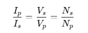
    relationship between the number of turns in the primary and secondary windings

    The primary is usually formed by a single loop made by the conductor to be measured. Although, it is possible to wind the driver making this happen more than once inside the “clamp”. The number of turns of the secondary, integrated in the probe, varies from 1000-2000, according to the models of the SCT013.

    Unlike voltage transformers, in a current transformer, the secondary circuit should never be opened, because induced currents could damage the component. For this reason, the sensors of SCT13 have protections: resistance burden in the sensors of output by voltage, or diodes of protection in the sensors of exit by the current.

    Assembly Diagrams


    To understand the connection of the sensor SCT013, we have to understand and solve three problems:

     Sensor output in intensity

     Adjustment of the voltage range

     Positive and negative stress


    SENSOR OUTPUT IN INTENSITY

    The SCT013 are current transformers, that is, the measurement is obtained as an intensity signal proportional to the current flowing through the cable,.  Processors, however, are only capable of measuring voltages.

    This problem is easy to solve. To convert the output in intensity into a voltage output, we only have to include a resistance (load resistance).

    With the exception of model SCT013-000, all other SCT013 models have an internal load resistance so that the output is a voltage signal of 1V. This is why it will not be a concern to worry about.

    Only in the case of SCT013-000, there is no resistance internal burden, so the output is a signal of ± 50mA. A resistance of 33Ω in parallel with the sensor will suffice.


    Positive and Negative Tensions

    Another problem we have to solve is that we are measuring alternating current, and the intensity induced in the secondary is alternating. After passing through the resistance burden, whether internal or external, the voltage output is also alternating.


    However, as we know, the analog inputs of the majority of processed currents, including Arduino, can only measure positive voltages.

    To measure the voltage at the transformer output, we have several options, ordered here from least to most recommended:

    1. Rectify the signal through a diode bridge, and measure the wave as positive values. Not advisable given that we lose information as to whether we are in the negative or positive half-period, and because we will have the voltage drop of the diode, and, even worse, the diode does not drive below a voltage meaning the signal will be distorted at the junctions by zero.
    2. Add an offset in DC by using two resistors and a capacitor that provide a midpoint between GND and Vcc. Much better if we also add an operational amplifier as a voltage follower.
    3. Add an ADC with differential input, which allows measurements of positive and negative voltages, such as the ADS1115. This is the option that we are going to use.

    Voltage Range Adaptation

    The last problem is the need to adapt the range of voltages at the sensor output. Arduino can only perform measurements between 0 and Vcc. In addition, the smaller the range, the greater loss of accuracy, so we should adapt to this range.

    On the other hand, we must remember that when it comes to AC voltage, RMS values are usually used. Briefly review the peak voltage and peak-to-peak equations:

    Formula for peak voltage of sinusoidal AC in pure resistance circuit

    Therefore, for a sensor with an output of ±1V RMS, the peak voltage is ±1.414V and the

    In the case of the SCT013-000, the output will be ±50mA. With an external load resistance of 33Ω, the output voltage is ±1.65V RMS, so the peak voltage is ±2.33V and the peak-to-peak voltage is 4.66V.

    Electric Connection


    We already have all the components to measure the network intensity with an SCT-013 sensor. We will use a sensor with voltage output ± 1V RMS and internal burden resistance, together, with an ADC like the ADS1115 in differential mode.

    Adjusting the gain of the ADS1115 to 2.048V will place it within the range of ± 1.414V. In the case of a 30A sensor we will have an accuracy of 1.87mA, and 6.25 mA for a 100A sensor.


    If you use an SCT013-000 with an output of ± 50mA, we will have to add an external load resistor of 33Ω and raise the gain of the ADS1115 to 4.096V to comply with the range of ± 2.33

    The connection, seen from Arduino, would only be the power supply of the ADS1115 module as we saw in the entry on the ADS1115.

    For the measurement, it is important that we use only one wire in the “clamp” If we use multiple conductors (two conductors for a single-phase installation and three for a three-phase installation), the role of the conductor will be abolished. This produces a zero inductance, and therefore produces an empty measurement.

    The SCT013 sensor has a Jack 3.5 connector, which is very common in the audio field but is not sufficient to use in our electronic projects. To be able to connect it, we must cut off the cable or get a female connector off our welding cable. Fortunately, these terminals are easy to get, but do not rule out cutting off the cables.

    If you don’t want to use an external ADC, you can also use a more traditional solution that adds a circuit that allows us to add a center offset.

    From now on, we will assume that you use an Arduino with Vcc 5V. If you use another processor or an Arduino model with another Vcc (for example, 3.3V), you should correct the part accordingly.

    When we added a 2.5V DC offset point, the final range was 1.08V to 3.92V, with Arduino powered at 5V over the analog input range.

    Code example.


    Assembly with ADS1115


    If you use a component with SCT013 with ±1V RMS output and ADS1115, the required code is similar to the code we see in the input to the ADS1115. You need to consult the Adafruit library for ADS1115.

    In order to sample the ADS1115 at a higher speed, we need to modify the file, ‘Adafruit_ADS1015.h’.

    With this modification, we will be able to reduce the sampling time from about 8-9 milliseconds (about 100 hertz) to about 1.8 milliseconds (about 500 hertz). As we leave the Nyquist frequency, we improve the measurement behavior.

    Another version uses the measured maximum and minimum values and then calculates the measured value based on the peak value. The result should be similar to that seen in the square sum example. To do this, you can replace this feature with the following features:

    We can see the results in the serial port monitor, and either draw them with a serial plotter, collect it in a larger project to display on a web page, or register it in SD.

    ASSEMBLY WITH RESISTANCE AND MEDIUM POINT

    In this case, the example is very simple and we only need to measure through analog input:


  • Why Use a Rogowski Coil?

    Why Use a Rogowski Coil?

    Overview

    Rogowski coils are specialized devices for measuring alternating current (AC) or high-speed current pulses, offering unique advantages for various applications. They are particularly useful in scenarios where flexibility, accuracy, and safety are crucial.

    Flexibility and Ease of Use

    Rogowski coils are flexible and can be wrapped around live conductors without disconnection, making them perfect for tight spaces or crowded electrical panels. This non-invasive installation reduces downtime and simplifies setup, especially in industrial or commercial settings.

    High Current and Frequency Capability

    Unlike traditional current transformers, Rogowski coils use an air core, preventing magnetic saturation. This allows them to accurately measure very high currents, such as those in power transmission or welding, and handle rapid changes, like transients or pulses, making them suitable for high-frequency applications.

    Safety and Cost-Effectiveness

    They are safer because they don’t produce high voltages when open-circuited, reducing electric shock risks. Additionally, their lightweight and simple design lowers construction and installation costs, offering a cost-effective solution for current measurement.

  • What is the Rogowski coil?

    What is the Rogowski coil?

    A Rogowski coil is a specialized electrical device designed for measuring alternating current (AC). It consists of a helical coil of wire wound uniformly around a non-magnetic, air-filled core, typically arranged in a toroidal (doughnut-like) shape. The coil is placed around a current-carrying conductor, and as the AC flows through the conductor, it generates a changing magnetic field. This changing magnetic field induces a voltage in the Rogowski coil, which is proportional to the rate of change of the current (the time derivative, di/dt).

    To obtain a direct measurement of the current, the induced voltage is typically processed through an integrator circuit, which converts the voltage signal into one proportional to the current itself. This makes the Rogowski coil particularly useful for applications requiring the measurement of high currents or fast transient currents, such as in power systems, industrial equipment, or research settings.

    Key Features and Advantages

    Air Core Design: Unlike traditional current transformers with iron cores, the Rogowski coil’s air core prevents magnetic saturation, allowing it to measure very high currents without distortion.
    Flexibility: Many Rogowski coils are designed to be flexible and can be opened to wrap around a conductor without needing to disconnect it, making installation straightforward and non-invasive.
    Wide Bandwidth: The coil can accurately measure currents with high-frequency components or rapid changes, such as those in lightning strikes or switching transients.

    Applications

    Power system monitoring and protection.
    Measuring high currents in welding or industrial processes.
    Research applications, such as analyzing transient phenomena.

  • Understanding Current Transformers and Their Applications

    Understanding Current Transformers and Their Applications

    Current transformers (CTs) are essential components in modern electrical systems. They allow for the safe measurement, monitoring, and control of high currents by producing a scaled‐down replica of the current flowing in a conductor. This article delves into how current transformers work, their various types, and the diverse applications in which they are used.

    What Are Current Transformers?

    Current transformers are devices designed to measure high electrical currents by generating a lower, proportional current that can be easily and safely measured by standard instruments. They serve as a bridge between high-power circuits and sensitive electronic equipment, ensuring that monitoring and control systems can operate without being exposed to dangerous high currents.

    How Do Current Transformers Work?

    At their core, current transformers work on the principle of electromagnetic induction. When a current flows through the primary conductor (which can be as simple as a single wire passing through the CT’s core), it produces a magnetic field. This magnetic field induces a current in the CT’s secondary winding. The ratio of the number of turns in the primary winding (often just the conductor itself) to the number of turns in the secondary winding determines the scale factor, which in turn sets the output current relative to the primary current.

    For example, a CT designed to provide a 1 A secondary output might have a ratio of 3000:1, meaning that when 3000 A flows in the primary circuit, the CT outputs 1 A. In many cases, the secondary output is standardized (such as 1 A, 5 A, or even a voltage output like 0.333 V) to simplify instrumentation and protection system designs.

    Types of Current Transformers

    There are several types of current transformers available, each suited to different applications:

    • Solid-Core (or Wound-Core) CTs:
      These are built with a fixed, solid magnetic core. They are typically used in new installations where the CT can be designed and manufactured as an integral part of the system.
    • Split-Core (or Open-Core) CTs:
      These CTs are designed with a hinge or split mechanism, allowing them to be clamped around an existing conductor without the need to disconnect it. This makes them ideal for retrofitting into operational systems and for applications where safety and ease of installation are paramount.
    • Bar-Type CTs:
      In these models, the CT is integrated directly into busbars or conductors, offering robust performance in high-current scenarios.
    • Rogowski Coils:
      Although technically not transformers in the traditional sense, Rogowski coils are used to measure alternating currents. They offer the advantage of being flexible and non-intrusive but require integrator circuits to produce a voltage output proportional to the current.

    Key Applications of Current Transformers

    Current transformers have a wide range of applications across various sectors:

    1. Energy Metering

    CTs are fundamental in electricity metering, allowing utilities and consumers to accurately measure energy consumption. By stepping down the high currents found in power distribution systems to measurable levels, CTs enable precise billing and energy monitoring.

    2. Protection Systems

    In protection relays and circuit breaker control, CTs provide crucial information about the current flowing through a circuit. This data helps in detecting abnormal conditions, such as overloads or short circuits, and initiates protective measures to isolate and protect equipment.

    3. Control and Monitoring

    Industrial automation and control systems use CTs to monitor current levels in motors, transformers, and other equipment. This monitoring helps in managing system performance and efficiency while ensuring that components operate within safe parameters.

    4. Renewable Energy Systems

    In renewable energy installations, such as wind farms and solar power plants, CTs are used to monitor the flow of electricity from generation to the grid. They ensure that systems operate efficiently and safely while providing data for performance optimization.

    5. Safety and Instrumentation

    CTs help in ensuring personnel safety by enabling the use of isolated measurement instruments. By providing a low-level secondary current, CTs allow for the safe operation of meters and sensors that would otherwise be at risk if connected directly to high-current circuits.

  • Wie ist die Ansprechzeit (tr) definiert?

    Die Sprungantwortzeit beschreibt das dynamische Verhalten eines Strommessumformers. Sie ist die Zeitspanne zwischen dem Erreichen von 90 % des Endwerts durch den Primärstrom und dem Erreichen von 90 % der endgültigen Amplitude durch das Ausgangssignal des Messumformers. Der Primärstrom muss einen Stromsprung mit einer vorgegebenen di/dt-Flanke (üblicherweise 100A/µs) und einer Amplitude nahe dem Nennstrom IPN  aufweisen.

  • Wie lässt sich die Magnetisierung des Strommessumformers vermeiden?

    Der verbleibende magnetische Fluss (Remanenz) im Kern hängt vom Sensortyp und vom magnetischen Material ab. Er verursacht eine zusätzliche Messabweichung, den sogenannten “magnetischen Offset”. Dessen Höhe hängt von der vorherigen Magnetisierung des Kerns ab und erreicht nach der Sättigung des Magnetkreises ihren Maximalwert.

    In folgenden Situationen kann eine Magnetisierung auftreten:

    1. Hoher Überlaststrom

    2. Unterbrechung der Stromversorgung (Stromausfall)

    Der durch Magnetisierung verursachte Offset verschwindet unter folgenden Bedingungen:

    1. Der durch Magnetisierung verursachte Offset verschwindet mit der Zeit von selbst (der Kern erholt sich langsam; wie schnell dies geschieht, hängt vom magnetischen Material ab).

    2. Er wird durch Entmagnetisieren des Sensors beseitigt, beispielsweise durch geeignetes Umkehren des Primärstroms oder durch einen speziellen Entmagnetisierungszyklus. Nach dem Entmagnetisieren kann der Sensor seine ursprüngliche Leistung wieder erreichen.

  • Kann ein Messumformer entmagnetisiert werden?

    Ablauf der Entmagnetisierung:

    Zur Entmagnetisierung des Magnetkerns eines Messumformers werden üblicherweise die folgenden Schritte angewendet:

    1. Wechselstromanregung: Eine niederfrequente Wechselstromquelle durchläuft mit dem Magnetkern dessen gesamte B-H-Hystereseschleife (die Kurve von Magnetfeldstärke und Magnetisierung). Dazu wird Wechselstrom angelegt, sodass die Magnetisierung des Kerns zwischen positiver und negativer Sättigung wechselt.

    2. Allmähliche Verringerung der Anregung: Nachdem der Kern die B-H-Schleife mindestens 5 vollständige Zyklen bei maximaler Amplitude durchlaufen hat, wird die Amplitude der Wechselstromanregung schrittweise verringert. Die Verringerung sollte höchstens 4 % pro Zyklus betragen, damit die Magnetisierung des Kerns gleichmäßig auf null zurückgeht (den Ursprung der B-H-Kurve).

    3. Zeitbedarf: Ein Entmagnetisierungsdurchlauf erfordert üblicherweise etwa 30 Zyklen bei einer niedrigen Frequenz, beispielsweise 500 Millisekunden bei 60 Hz.


    Besondere Hinweise für Geräte mit geschlossenem Regelkreis:

    Bei Messumformern mit geschlossenem Regelkreis (Geräten mit einer Kompensationsspule) ist besondere Sorgfalt erforderlich, da die Kompensationsspule der Entmagnetisierung entgegenwirken kann. Dadurch erreicht der Kern möglicherweise seinen neutralen Zustand nicht. Zusätzliche Schritte können daher nötig sein, um eine ordnungsgemäße Entmagnetisierung sicherzustellen.

    Teilweise Entmagnetisierung:

    Alternativ lässt sich eine teilweise Entmagnetisierung erreichen, indem ein bestimmtes Signal mit entgegengesetzter Polarität zur Magnetisierung des Kerns angelegt wird. Diese Methode ist jedoch aufwendiger, da Amplitude und Dauer des Signals präzise bestimmt werden müssen, um die Magnetisierung wirksam zu verringern, ohne über das Ziel hinauszuschießen oder zu wenig zu kompensieren.

    Wenn eine bestimmte Anwendung gut verstanden ist, lässt sich das erforderliche Korrektursignal in der Praxis empirisch bestimmen und bei Bedarf zur Entmagnetisierung anlegen.

    Die Entmagnetisierung ist wichtig, um die Genauigkeit und Zuverlässigkeit der Messungen eines Messumformers zu erhalten, insbesondere nach starken magnetischen Einflüssen oder längerem Gebrauch.

  • Regarding the effects of different Vref connections on the output.

    Regarding the effects of different Vref connections on the output


    Let’s take a product with a supply voltage of +5V and an output of 2.5V ± 0.625V with a precision of 1% as an example.
    Our Vref pin serves two functions: one is to act as a reference point for output, commonly used in differential input acquisition devices; the other function is for single-ended input acquisition devices, where it is used to control the sensor output, making the static output (2.5V) more accurate. It only affects the static output (2.5V when there is auxiliary power and no input signal) and does not affect the amplification (0.625V).
    Due to the discreteness of product parameters, sensors cannot be perfectly identical and ideal, and there will always be some degree of error. For most of our products, the static reference point error is within ±15mV. This means the static output of 2.5V (with 0V or GND as the reference point) will be between 2.485V and 2.515V, which is considered within the acceptable range.
    For example, for a product with a power supply of +5V and an output of 2.5V ± 0.625V with a precision of 1%:

    If the output is referenced to 0V (GND), we calibrate it as follows:
    First, check if the Vref voltage meets the requirements (standard is 2.5V ± 1%, generally no more than 0.5%).
    The second step is to adjust the static output to between 2.485V and 2.515V (i.e., 2.5V ± 15mV).
    The third step is to apply the input signal to the rated input and adjust the output to within 2.5V + (0.625V ± 1%).
    Finally, check if the output at 10% of the rated input is accurate. If there is significant error, adjust the zero-point component for correction. Then, check if the zero-point and full-scale values meet the requirements. If everything is correct, the product moves on to the next process step.

    If the output is referenced to Vref, we adjust it as follows:

    First, check if the Vref voltage meets the requirements (standard is 2.5V ± 1%, generally no more than 0.5%).
    The second step is to adjust the static output to between 2.485V and 2.515V (i.e., 2.5V ± 15mV).
    The third step is to connect the black probe of the multimeter to the Vref point, apply the input signal to the rated input, and adjust the output to within 0.625V ± 1%.
    Finally, check if the output at 10% of the rated input is accurate. If there is significant error, adjust the zero-point component for correction. Then, check if the zero-point and full-scale values meet the requirements. If everything is correct, the product moves on to the next process step.

    If a product adjusted using the first method is used in a differential input acquisition device, the acquired signal will be inaccurate and may even produce negative output errors.
    If a product adjusted using the second method is used in a single-ended input acquisition device, the acquired signal will also be incorrect and may result in overflow errors.

    By default, our products are calibrated using the first method (referenced to 0V/GND), as most customers request this.

    Example 1: A product calibrated using the first method, with Vref = 2.510V and Vout = 2.505V in the static state. This product is qualified, and the precision is acceptable. However, when used in a differential input acquisition device, since Vout is lower than Vref, the static output will be negative, which is incorrect.
    null

    Example 2: A product calibrated using the second method, with Vref = 2.510V and Vout = 2.520V in the static state. This product is also qualified, as the zero-point error does not exceed 15mV. However, when used in a single-ended input acquisition device, the output of 2.520V exceeds the calibrated 15mV error, and the full-scale value will also be higher, which could reach up to 2% in extreme cases, affecting the customer’s use.
    Now that some customers have reported this type of error, we are asking them to provide calibration requirements to correct the issue. Sales representatives are also being asked to label products based on different calibration methods to ensure correct production for customers.
    null

  • How to calculate transformer short circuit current?


    To calculate the input current of a transformer, you can use the following formula based on the transformer’s power rating, input voltage, and efficiency. The input current depends on the power demand on the secondary side (load), and this can be calculated for both single-phase and three-phase transformers.

    1. Single-Phase Transformer Input Current Calculation

    For a single-phase transformer, the input current IinputI_{\text{input}} can be calculated using the formula:

    Iinput=PoutVprimary×ηI_{\text{input}} = \frac{P_{\text{out}}}{V_{\text{primary}} \times \eta}​​

    Where:

    • IinputI_{\text{input}} = Input Current (in Amperes)
    • PoutP_{\text{out}} = Output Power (in Watts or VA)
    • VprimaryV_{\text{primary}} = Primary Voltage (in Volts)
    • η\eta = Efficiency of the transformer (expressed as a decimal)

    If the efficiency is not given, it can be assumed based on typical transformer efficiency (for instance, 0.98 for a high-efficiency transformer).

    2. Three-Phase Transformer Input Current Calculation

    For a three-phase transformer, the input current IinputI_{\text{input}} is calculated with a similar formula but with an additional factor for three-phase power:

    Iinput=Pout3×Vprimary×ηI_{\text{input}} = \frac{P_{\text{out}}}{\sqrt{3} \times V_{\text{primary}} \times \eta}​​

    Where:

    • IinputI_{\text{input}} = Input Current (in Amperes)
    • PoutP_{\text{out}} = Output Power (in Watts or VA)
    • VprimaryV_{\text{primary}} = Primary Line-to-Line Voltage (in Volts)
    • η\eta
    • 3\sqrt{3} = 1.732, a factor used for three-phase power

    3. Example Calculation (Three-Phase Transformer)

    Suppose you have a 500 kVA transformer, with a primary voltage of 11 kV (11,000 V) and an efficiency of 98%.

    Step 1: Determine Output Power:

    For a 500 kVA transformer, the power PoutP_{\text{out}} is 500,000 VA (since 1 kVA = 1,000 VA).

    Step 2: Apply the Formula:

    Iinput=500,0003×11,000×0.98I_{\text{input}} = \frac{500,000}{\sqrt{3} \times 11,000 \times 0.98}

    Iinput=500,0001.732×11,000×0.98I_{\text{input}} = \frac{500,000}{1.732 \times 11,000 \times 0.98}

    Iinput=500,00018,577.176≈26.92 AI_{\text{input}} = \frac{500,000}{18,577.176} \approx 26.92 \, \text{A}

    So, the input current for the primary side of the transformer is approximately 26.92 A.

    Important Notes:

    • The output power PoutP_{\text{out}} is usually given in kVA or VA. To convert from kW to VA, use the apparent power formula Pout=kWpower factorP_{\text{out}} = \frac{\text{kW}}{\text{power factor}} if necessary.
    • Efficiency η\eta
    • For three-phase systems, make sure you use the line-to-line primary voltage.

    This calculation helps determine how much current is drawn on the primary side of the transformer based on the output load.

  • What is current transformer Burden?

    In a current transformer (CT), the burden refers to the total impedance (resistance and reactance) presented by the connected measuring devices, such as ammeters, relays, or meters, to the secondary winding of the CT. It is usually expressed in volt-amperes (VA) at a specific secondary current (typically 1A or 5A) and can include the impedance of the connecting wires and instruments.

    Key Points:

    1. Burden Components: The burden consists of the impedance of the connected devices (like meters, protection relays, and wires) which draw power from the CT’s secondary winding.
    2. Burden Rating:
      • CTs are rated for a maximum burden in VA. For example, a CT rated for 10 VA means that the connected load should not exceed 10 VA.
      • If the burden exceeds the CT’s rated value, it can cause errors in current measurement or protection malfunctions because the CT may not be able to maintain its accuracy or properly step down the current.
    3. Importance of Proper Burden:
      • The burden affects the accuracy of the CT. If the burden is too high (i.e., the impedance of the connected devices is too large), the CT will not provide an accurate current transformation, leading to incorrect measurements or protection relay malfunctions.
      • On the other hand, if the burden is too low, the CT may operate closer to saturation, which also leads to inaccuracies.
    4. Practical Consideration:
      • When installing a CT, it is crucial to calculate the burden of all connected devices and ensure it falls within the CT’s rated burden for proper performance.

    In summary, the burden is the load imposed on the secondary winding of the current transformer, and ensuring it is within the CT’s rated capacity is essential for accurate current measurement and safe operation.

  • Wie schließt man einen Stromwandler an?

    1. Einphasiger Stromkreis:

    • Connection Mode: A single current transformer is connected in series with the live wire or neutral wire of the circuit.
    • Application: This is used for measuring single-phase current, power, and providing protection against single-phase faults, such as ground faults or short circuits.
    • Diagram:

    2. Unvollständige Sternschaltung (V-Schaltung) mit zwei Stromwandlern (dreiphasiger Stromkreis):

    • Connection Mode: Two current transformers are connected in a “V” configuration (incomplete star), where the primary windings are connected to two of the three-phase conductors. The secondary windings are then connected together to form a measuring point.
    • Application: This connection is used to measure three-phase current, power, and to protect the system from phase-to-phase short-circuit faults. Although only two transformers are used, it provides sufficient information about the three-phase system for protection and measurement in a balanced system.
    • Diagram:

    3. Stromdifferenz zwischen zwei Phasen mit zwei Stromwandlern (Schutz bei Phasendifferenzen):

    • Connection Mode: Two current transformers are placed in two different phases (e.g., Phase A and Phase B), and their secondary windings are connected to each other to detect any current difference between these phases.
    • Application: This configuration is used for measuring one-phase current and for protecting against phase-to-phase short-circuit faults. It is based on detecting differences in the phase currents, which indicates a fault between phases.
    • Diagram:

    4. Sternschaltung mit drei Stromwandlern (dreiphasiges Vierleitersystem):

    • Connection Mode: Three current transformers are connected in a star (wye) configuration. Each CT is placed on one phase of a three-phase system, and the secondary windings are connected to a common point (neutral).
    • Application: This setup is suitable for measuring three-phase current, power, and protecting the system in a three-phase four-wire system. It can detect any form of fault, including ground faults, phase-to-phase faults, and phase-to-neutral faults.
    • Diagram:
  • What is Residual Current Sensor?

    A Residual Current Sensor (RCS) is an electrical safety device designed to detect residual current (also known as leakage current) in a circuit. Residual current occurs when there is an imbalance between the current flowing into a system (through the live wire) and the current returning from the system (through the neutral wire). This imbalance indicates that some current is leaking to the ground, often due to insulation failure, faulty wiring, or a person coming into contact with the electrical system.

    How Does a Residual Current Sensor Work?

    1. Current Imbalance Detection: The RCS measures the difference between the current in the live wire and the neutral wire. Under normal operating conditions, the current flowing through these two wires should be equal. If there is a discrepancy, it means current is leaking somewhere.
    2. Detection Threshold: If the difference between the live and neutral current exceeds a certain threshold (usually set to a few milliamps, such as 10 mA or 30 mA, depending on the application), the sensor detects it as residual current.
    3. Activation of Safety Mechanism: When residual current is detected, the sensor typically signals a protective device, such as a Residual Current Device (RCD) or Ground Fault Circuit Interrupter (GFCI). These devices will quickly disconnect the power to prevent hazards like electric shock or fire.

    Key Features of a Residual Current Sensor:

    • High Sensitivity: RCS devices can detect very small current differences, often in the range of milliamps (mA).
    • Non-Intrusive: The sensor can monitor current flow without interrupting the circuit.
    • Rapid Response: It triggers safety mechanisms immediately upon detecting leakage, minimizing risks.
    • Accuracy: Modern RCS units provide precise detection and monitoring of residual current to avoid nuisance tripping.

    Applications:

    1. Household Electrical Safety: RCS is widely used in household RCDs and GFCIs to protect users from electric shocks, particularly in wet areas like kitchens and bathrooms.
    2. Industrial Systems: In industrial environments, RCS devices monitor equipment to detect insulation failures or potential fault conditions that could lead to electrical hazards.
    3. Renewable Energy: RCS is also employed in renewable energy systems, such as solar power installations, to ensure safe operation and prevent electrical leakage to ground.

    Benefits:

    • Prevention of Electric Shock: RCS can detect when current flows through a person or faulty wiring to the ground, preventing serious injury.
    • Fire Prevention: By detecting leakage currents caused by insulation failure, the RCS can help prevent electrical fires.
    • Compliance with Safety Standards: Residual current sensors are essential for meeting electrical safety regulations in homes, offices, and industrial settings.

    In summary, a Residual Current Sensor is a critical safety device that continuously monitors circuits for leakage current, helping to protect people and property from electrical hazards by detecting imbalances in current flow and triggering protective mechanisms.

  • What is a Rogowski coil and how does it work?

    Rogowski coil also called differential current sensor, it is a “hollow” circular coil, arranged around the conductor, so that an alternating magnetic field generated by the current induces a voltage in the coil. The coil is actually a ransformer coupled to the conductor under test, and the voltage directly output from the coil is proportional to the rate of change of current, e.g. @50Hz/1kA Vout=85mV, @60Hz/1kA Vout=85*60/50=102mV. If you want to obtain the current waveform or current value that doesn’t matter to frequency also need to add the integral circuit to achieve 90° phase shift compensation and frequency equalization.

    RF series is a flexible current sensor based on Rogowski coil principle, which is in small size, light weight and easy to install and offers a choice of different sizes, which can also be customized design of the customer requires a special order. It has no magnetic saturation and a shielding layer to resist the influence of external magnetic field, so stable measurements can be achieved in the range of low current to hundreds of kA. The flexible rogowski coil is an extremely comfortable solution for current measurement,
    particularly suited to current monitoring and electrical retrofitting, can be used in many cases where a traditional current transformer (CT) is not available, or can replace it.Systems that use an ADC chips(ADS131M04) or a power metering ICs(ADE7753) that support the Rogowski coil principle are even more advantageous.

  • Wie wählt man einen Stromwandler aus?
    1. Art des zu messenden Stroms bestimmen:
      • Stellen Sie fest, ob es sich bei dem zu messenden Strom um Wechselstrom (AC) oder Gleichstrom (DC) handelt. Die meisten Stromwandler sind für Wechselstrom ausgelegt. Wenn Sie Gleichstrom messen müssen, benötigen Sie daher einen geeigneten Gleichstromwandler.
    2. Nennstrom bestimmen:
      • Ermitteln Sie den maximal zu messenden Strom. Stromwandler sind für bestimmte Strombereiche ausgelegt. Die Wahl des passenden Bereichs ist daher für genaue Messungen entscheidend.
    3. Erforderliche Genauigkeit bestimmen:
      • Je nach Anwendung gelten unterschiedliche Genauigkeitsanforderungen. Bei der Stromerzeugung und -übertragung ist beispielsweise meist eine höhere Genauigkeit erforderlich als bei manchen industriellen Anwendungen. Bestimmen Sie die für Ihre Anwendung nötige Genauigkeit und wählen Sie einen Stromwandler, der diese Anforderung erfüllt.
    4. Erforderliche Bürde bestimmen:
      • Die Bürde ist die maximale Last, die der Stromwandler versorgen kann. Sie wird üblicherweise in VA (Voltampere) angegeben. Wählen Sie einen Stromwandler mit einer für Ihre Anwendung ausreichenden zulässigen Bürde.
    5. Benötigte Ausgangsart berücksichtigen:
      • Bestimmen Sie, ob ein Spannungs- oder Stromausgang benötigt wird, und wählen Sie einen Stromwandler mit dem entsprechenden Ausgang.
    6. Baugröße und Montageanforderungen berücksichtigen:
      • Wählen Sie einen Stromwandler, dessen Baugröße und Montageart für Ihre Anwendung geeignet sind.
    7. Kompatibilität prüfen:
      • Stellen Sie sicher, dass der Stromwandler mit Ihren Messgeräten kompatibel ist und die einschlägigen Sicherheitsnormen erfüllt.
  • What is the difference between current transformer and voltage transformer?
    • Current Transformers (CTs): Measure and step down current for use in measurement, monitoring, and protection systems. They are connected in series with the circuit, providing a lower current proportional to the high current in the system for safe, accurate measurement.
    • Voltage Transformers (VTs): Measure and step down voltage for similar purposes. They are connected in parallel to the circuit, delivering a reduced voltage proportional to the high voltage for safe analysis and control.

    In essence, CTs are used for current measurement and VTs for voltage measurement, both essential for protection, control, and monitoring in electrical power systems.

  • Why current transformer secondary is always short circuited?

    The secondary of a current transformer (CT) is always short-circuited (or connected to a low-impedance load like a meter or relay) for several important reasons related to safety and proper functioning:

    1. Voltage Rise on an Open Secondary:

    • Dangerous Voltage: If the secondary winding of a CT is left open while current flows in the primary winding, it behaves like a step-up transformer. Since the primary winding carries high current and the secondary winding has many turns, an open circuit can cause the voltage in the secondary to increase to dangerously high levels.
    • Insulation Breakdown and Safety Hazard: The high induced voltage can exceed the insulation rating of the transformer, leading to insulation breakdown and a potential shock hazard to personnel or equipment damage.

    2. Core Saturation:

    • Magnetic Core Saturation: In normal operation, the secondary current creates a magnetic field that opposes and cancels out most of the magnetic flux created by the primary current. If the secondary is open, no current flows in the secondary, and the magnetic flux in the core increases to very high levels.
    • Core Overheating: The excessive magnetic flux can saturate the CT core, leading to overheating and potential damage to the transformer. This can result in permanent damage to the CT, reducing its accuracy and reliability.

    3. Accurate Measurement:

    • Current Proportionality: CTs are designed to measure current, and they rely on the secondary current being proportional to the primary current (following the turns ratio). If the secondary is open, this relationship is broken, and no accurate current measurement can be made.
    • Protection System Failure: CTs are often used in protective relays to monitor overcurrent or fault conditions. An open secondary may prevent the proper operation of protective devices, potentially leading to system failures or unprotected faults.

    4. Reduced Burden on the Secondary:

    • Minimizing Burden: A CT is designed to operate with a very low burden (load) on its secondary side to maintain accuracy. Short-circuiting the secondary or connecting it to a low-impedance load ensures that the CT operates within its designed parameters, providing accurate current measurements without overloading the core or secondary windings.
  • Wie liest man einen Stromwandler (CT) mit Arduino aus?

    Wie liest man einen Stromwandler (CT) mit Arduino aus?

    Um einen Stromwandlersensor an einen Arduino anzuschließen, muss dessen Ausgangssignal so aufbereitet werden, dass es die Anforderungen der Arduino-Analogeingänge erfüllt: Es muss eine positive Spannung zwischen 0 V und der Referenzspannung des Analog-Digital-Wandlers (ADC) anliegen.

    Als Beispiele dienen ein Arduino-Board mit 5 V Betriebsspannung und ein EmonTx mit 3,3 V. Achten Sie darauf, bei Ihren Berechnungen die für Ihren Aufbau passenden Werte für Versorgungsspannung und Vorspannung zu verwenden.

    Die Schaltung besteht aus zwei Hauptteilen: Sie wandeln den Strom des Stromwandlers in eine Spannung mit der richtigen Amplitude um und verschieben diese Spannung in die Mitte des ADC-Eingangsbereichs.

    Die angegebenen Spannungen und Ströme gelten für einen 5-V-Arduino mit einem Analogeingangsbereich von 0 bis 5 V. Bei einer Sinuswelle entspricht dies etwa 1,6 V Effektivwert (RMS). Beim emonTx V2 und V3 sowie beim emonPi beträgt der Analogeingangsbereich 0 bis 3,3 V. Die Mittenspannung liegt daher bei 1,65 V, und die analoge Eingangsspannung schwankt zwischen 0 und 3,3 V (etwa 1 V Effektivwert (RMS) bei einer Sinuswelle). Beim emonTx4 und emonPi2 beträgt der Analogeingangsbereich 0 bis 1 V. Er ist für Stromwandler mit 0,333 V Effektivwert (RMS) am Ausgang vorgesehen, die keinen Bürdenwiderstand benötigen. Daher entfällt dieser Widerstand.

    ct-sensors-circuit1.png

    Ausführliche Anleitung


  • Why current transformer secondary should not be open?

    The secondary of a current transformer (CT) should never be left open when current is flowing through the primary because doing so can create dangerous high voltages. Here’s why:

    1. Induced High Voltage:

    • A current transformer operates on the principle of electromagnetic induction. The current in the primary winding induces a current in the secondary winding. If the secondary is left open, there is no current flowing through it, which prevents the magnetic field from opposing the primary current.
    • As a result, the magnetic flux in the core increases dramatically, which leads to a very high voltage being induced in the secondary winding. This high voltage can damage the CT insulation or create a serious safety hazard for anyone nearby.

    2. Saturation and Core Damage:

    • With no load (open secondary), the core of the CT may become saturated due to the high magnetic flux. Prolonged exposure to this condition can permanently damage the CT core by altering its magnetic properties, reducing its accuracy and performance over time.

    3. Safety Hazards:

    • The high voltage produced across the open secondary can be lethal and may damage connected equipment. In some cases, the voltage can even cause arcing, which presents a significant fire or electrical shock risk.

    4. Inaccuracy in Measurements:

    • If the CT secondary is open, it cannot perform its primary function, which is to accurately measure current. With the secondary circuit open, there is no reliable way to measure the current in the primary circuit, which can lead to incorrect readings and relay malfunctions in protection systems.


  • Wie liest man einen Stromsensor mit Arduino aus?

    Nehmen wir das Modell HSTS016L als Beispiel: Es kann Stromwerte von 10 A bis 200 A messen. Bei diesem Stromsensor mit teilbarem Kern lässt sich der Kern öffnen und schließen, ohne das bestehende System zu verändern. Das Messkabel wird einfach in den Kern eingelegt und dieser zugeklappt. Die Ausgangsspannung des Sensors beträgt 2,5 V ± 0,625 V. Sein Ausgangsspannungsbereich von 1,875 V bis 3,125 V eignet sich auch für 3,3-V-Analogeingänge, insbesondere bei den Mikrocontrollern Arduino Nano und NodeMCU.


    Der Sensor hat vier Anschlüsse: ROT (5-V-Eingang), SCHWARZ (0 V, Masse), GELB (Analogausgang) und WEISS (Analogsignal zur Kalibrierung). Da die Versorgungsspannung möglicherweise nicht genau 5 V beträgt, benötigen wir einen zusätzlichen Analogeingang, um den tatsächlichen Mittelpunkt am weißen Anschluss zu messen. Der Arduino UNO hat sechs Analogeingänge (A0–A5). Einen davon können wir zur Messung des Wechselstroms und einen weiteren zur Kalibrierung verwenden. Die Analogeingänge bilden Eingangsspannungen zwischen 0 und 5 V mit einer Auflösung von 4,9 mV pro Einheit (5,00 V / 1023 Einheiten) auf ganzzahlige Werte zwischen 0 und 1023 ab.


    Wir verbinden ROT mit dem 5-V-Eingang, SCHWARZ mit Masse, GELB mit dem Analogeingang A1 und WEISS mit dem Analogeingang A2. Es wird dringend empfohlen, den Arduino Uno und den Sensor über ein 12-V-Netzteil zu versorgen. Bei einer 5-V-Versorgung über USB entsteht ein anfänglicher Offsetwert, den Sie beim Hochladen des Codes möglicherweise manuell ergänzen müssen.


    // Anschluss zur Messung des Stromwerts (A0 ist für die Tastenfunktion des LCD Display Shield reserviert)
    int currentAnalogInputPin = A1;  
    // Anschluss zur Kalibrierung des Offset-Mittelwerts
    int calibrationPin = A2; 
    // Wert zur manuellen Korrektur des anfänglichen Offsets eingeben
    float manualOffset = 0.00;
    // Bei Verwendung eines Hall-Effekt-Stromwandlers den Wert nach folgender Formel eingeben: mVperAmp = maximaler Spannungsbereich (in Millivolt) / Nennstrom des Stromwandlers
    float mVperAmpValue = 12.5;        
    // Maximale Versorgungsspannung des Analogeingangs: beim Arduino Uno oder Mega 5000 mV, beim Arduino Nano oder NodeMCU 3300 mV
    float supplyVoltage = 5000;
    /* zum Einlesen eines Abtastwerts für die spätere Offsetkorrektur */
    float offsetSampleRead = 0;        
     /* zum Einlesen eines Abtastwerts einschließlich des Werts currentOffset1*/
    float currentSampleRead  = 0;     
      /* zur Zeitmessung für jeden Abtastwert. Theoretisch wird jede Millisekunde ein Abtastwert erfasst */
    float currentLastSample  = 0;     
      /* Summe der Abtastwerte */
    float currentSampleSum   = 0;     
      /* zum Zählen der Abtastwerte. */
    float currentSampleCount = 0;     
        /* zur Berechnung des Mittelwerts aller Abtastwerte als Analogwert*/
    float currentMean ;            
      /* Quadratwurzel aus currentMean als Analogwert */
    float RMSCurrentMean ;             
       /* endgültiger Strom-Effektivwert (RMS)*/
    float FinalRMSCurrent ;           
    void setup()                                 /* Code, der einmal ausgeführt wird */
    {
            Serial.begin(9600);                 /* Messwerte im seriellen Monitor mit 9600 Baud anzeigen */
    }
    void loop()
    {
            /* 1- Wechsel- und Gleichstrommessung */
            if(micros() >= currentLastSample + 200)                     /* alle 0,2 Millisekunden einen Messwert erfassen */
              {
               /* Abtastwert einschließlich Offsetwert einlesen*/
               currentSampleRead = analogRead(currentAnalogInputPin)-analogRead(calibrationPin); 
              /* Analogwerte der einzelnen Messungen aufsummieren*/
               currentSampleSum = currentSampleSum + sq(currentSampleRead) ;
               /* Zähler für den nächsten Abtastwert erhöhen */
               currentSampleCount = currentSampleCount + 1; 
               /* Zeitwert für den nächsten Zyklus zurücksetzen*/
               currentLastSample = micros(); 
              }
            /* nach 4000 Abtastwerten oder 800 Millisekunden (0,8 Sekunden) folgenden Code ausführen*/
            if(currentSampleCount == 4000) 
              {
                /* Mittelwert der aufsummierten Analogwerte*/
                currentMean = currentSampleSum/currentSampleCount;
                 /* Quadratwurzel des Mittelwerts*/
                RMSCurrentMean = sqrt(currentMean);
                 /* endgültigen Strom-Effektivwert (RMS) berechnen*/
                FinalRMSCurrent = (((RMSCurrentMean /1023) *supplyVoltage) /mVperAmpValue)- manualOffset;
                  /* liegt der gemessene Strom bei höchstens 1 %, den Stromwert auf 0 A setzen*/
                if(FinalRMSCurrent <= (625/mVperAmpValue/100))
                { FinalRMSCurrent =0; }
                Serial.print(” Der Strom-Effektivwert (RMS) beträgt: “);
                Serial.print(FinalRMSCurrent,decimalPrecision);
                Serial.println(” A “);
                currentSampleSum =0;                                 /* Summe der Abtastwerte für den nächsten Zyklus zurücksetzen */
                currentSampleCount=0;                                 /* Anzahl der Abtastwerte für den nächsten Zyklus zurücksetzen */
              }
    }
  • Why does a transformer not work with direct current?

    A transformer does not work with direct current (DC) because its operation relies on changing magnetic fields, which DC does not provide. Here’s a detailed explanation of why transformers are ineffective with DC:

    1. Principle of Operation:

    • Transformers work based on Faraday’s Law of Electromagnetic Induction, which states that a changing magnetic field in the core induces an electromotive force (EMF) or voltage in the secondary winding.
    • This changing magnetic field is produced by an alternating current (AC), which constantly fluctuates and reverses direction, causing the magnetic flux in the transformer core to vary.

    2. No Changing Magnetic Field in DC:

    • DC provides a constant current that does not change direction or magnitude over time.
    • Since there is no fluctuation in the current, the magnetic flux in the transformer core remains constant. Faraday’s Law requires a time-varying flux to induce a voltage in the secondary winding, so no voltage is generated when DC is applied.

    3. Core Saturation:

    • When DC is applied to the primary winding, it creates a constant magnetic flux in the transformer core, which can quickly lead to core saturation.
    • In core saturation, the core’s magnetic material is fully magnetized, and it cannot carry any additional flux. This results in a significant increase in primary current, which can cause overheating, insulation failure, and potentially damage the transformer.

    4. High Heat Generation:

    • Because the resistance of the transformer windings is relatively low, a constant DC current can cause a large amount of power dissipation in the form of heat. This can quickly overheat and damage the windings and insulation of the transformer.

    5. Absence of Induced Voltage:

    • In AC, the continuous change in current induces a voltage in the secondary winding through the process of mutual induction. Since DC does not create this changing current, no voltage is induced in the secondary winding, meaning the transformer cannot step up or step down the voltage with DC input.

    Conclusion:

    • Transformers are designed to work with alternating current (AC) because the changing nature of AC creates the necessary varying magnetic field for voltage induction. When DC is applied, the lack of a varying magnetic field prevents the transformer from functioning, and prolonged use with DC can lead to overheating and failure.
  • Why use current transformer?

    A current transformer (CT) is a vital electrical device used in high-power systems for the accurate measurement of alternating current (AC). It operates on the principle of electromagnetic induction, enabling the safe reduction of high current levels to a manageable value for measurement or protection. Below is a detailed explanation of its construction and working principles:

    1. Construction:

    A current transformer consists of two main windings: the primary winding and the secondary winding.

    • The primary winding is typically connected in series with the high-current-carrying conductor, whose current needs to be measured.
    • The secondary winding is connected to measuring instruments like ammeters, protective relays, or metering devices. The primary winding often consists of just one turn, while the secondary winding has a significantly higher number of turns.

    2. Turns Ratio:

    The turns ratio between the primary and secondary windings is a crucial parameter and is usually very high, often in the range of 100:1 to 5000:1. This means the secondary winding has many more turns compared to the primary winding. This ratio determines the magnitude of the current transformation and helps scale down the high current to a level suitable for standard measuring devices.

    3. Electromagnetic Induction:

    When an alternating current flows through the primary winding, it generates a corresponding alternating magnetic field around the conductor. According to Faraday’s Law of Electromagnetic Induction, this changing magnetic flux induces a proportional voltage in the secondary winding. The magnitude of the induced voltage and the resulting current in the secondary is dependent on the turns ratio.

    4. Step-Down Effect:

    The CT effectively steps down the high current from the primary side to a much lower current on the secondary side. While the turns ratio governs the reduction, the CT ensures that the secondary current is a scaled, proportional version of the primary current. For instance, a current transformer with a turns ratio of 1000:1 will produce 1 ampere in the secondary circuit when 1000 amperes flow in the primary conductor. This step-down effect enables standard measuring instruments, which are designed for low current ranges, to monitor the current accurately.

    5. Burden:

    The burden refers to the load connected to the CT’s secondary winding, which can be an ammeter, protective relay, or another measuring device. The impedance of this burden significantly affects the CT’s accuracy and performance. For accurate measurement, the burden impedance must match the CT’s specified range. If the burden is too high, the accuracy may be compromised, and in extreme cases, it may even damage the CT.

    6. Current Ratio:

    The current ratio of a CT is defined as the ratio of the primary current to the secondary current and is determined by the turns ratio. It is a fixed value for any given CT. For example, in a CT with a 1000:1 turns ratio, 1000 amperes in the primary circuit will produce 1 ampere in the secondary circuit. This consistent current ratio allows for the easy conversion of high primary currents into lower secondary currents for safe monitoring and protection.

    7. Accuracy Class:

    Current transformers are categorized into various accuracy classes based on their precision under specified conditions. The accuracy class defines the maximum permissible error in the measurement. The common accuracy classes are 0.1, 0.2, 0.5, 1, and 3, with class 0.1 offering the highest accuracy. CTs with higher accuracy are typically used in metering applications, whereas those with lower accuracy may be sufficient for protection purposes.

    The current transformer operates by stepping down high AC currents in a power system to a safer and manageable level, using the principle of electromagnetic induction and a high turns ratio. The CT’s secondary current is proportional to the primary current, which enables accurate measurement and protection of electrical systems. Proper matching of the CT’s burden and adherence to its accuracy class ensures reliable performance in various applications.

  • Wie misst man Gleichstrom mit einem Hall-Sensor?

    Komponenten:

    1. Hall-Sensor: Erfasst das Magnetfeld, das durch den Strom in einem Leiter entsteht, und gibt eine zur Magnetfeldstärke proportionale Spannung aus.
    2. Stromversorgung: Versorgt den Sensor mit Leistung und liefert eine Referenzspannung für die Berechnungen.
    3. Last: Schließt den Stromkreis, sodass Strom durch den Leiter fließen kann.
    4. Multimeter: Misst die Ausgangsspannung des Hall-Sensors.

    Schritte zur Messung von Gleichstrom:

    1. Komponenten verbinden: Schließen Sie den Hall-Sensor, die Stromversorgung und die Last gemäß den Anweisungen des Herstellers an.
    2. Sensor in der Nähe des Leiters platzieren: Richten Sie den Sensor so aus, dass das Magnetfeld des Leiters senkrecht auf seine Messfläche trifft.
    3. Stromversorgung einschalten: Schalten Sie die Stromversorgung ein, um den Stromkreis und den Hall-Sensor mit Spannung zu versorgen.
    4. Ausgangsspannung messen: Stellen Sie das Multimeter auf Spannungsmessung ein und verbinden Sie es mit dem Ausgang des Hall-Sensors.
    5. Ausgangsspannung notieren: Die gemessene Spannung hängt unmittelbar von der Stärke des Magnetfelds ab, das durch den Strom im Leiter entsteht.
    6. Strom berechnen: Berechnen Sie den Strom anhand der Empfindlichkeit des Sensors (üblicherweise in mV/Gauss oder V/Tesla angegeben), der Referenzspannung der Stromversorgung und des proportionalen Zusammenhangs zwischen Magnetfeld und Strom.

    Wichtige Hinweise:

    • Kalibrierung: Hall-Sensoren müssen möglicherweise kalibriert werden, um Temperaturschwankungen und andere Einflüsse auszugleichen und eine genaue Strommessung zu ermöglichen.
    • Lineares Verhalten: Stellen Sie sicher, dass der Hall-Sensor für optimale Ergebnisse innerhalb seines linearen Bereichs betrieben wird.

    Wenn Sie diese Schritte befolgen, können Sie mithilfe eines Hall-Sensors Gleichstrom genau messen.

  • Wie misst man Wechselstrom mit einem Hall-Sensor?

    Komponenten:

    1. Hall-Sensor: Erfasst das Magnetfeld, das durch den Wechselstrom im Leiter entsteht, und gibt eine zum Magnetfeld proportionale Spannung aus.
    2. Last: Eine Last (z. B. ein Widerstand) schließt den Stromkreis, sodass Strom fließen kann.
    3. Oszilloskop: Misst die Ausgangsspannung des Hall-Sensors und macht die Wechselstromkurve sichtbar.

    Schritte zur Messung von Wechselstrom:

    1. Komponenten verbinden:
      • Schließen Sie den Hall-Sensor und die Last gemäß den Anweisungen des Herstellers an. Der Sensor muss korrekt mit der Versorgungsspannung verbunden und passend in der Nähe des stromführenden Leiters positioniert sein.
    2. Sensor positionieren:
      • Platzieren Sie den Hall-Sensor in der Nähe des wechselstromführenden Leiters. Achten Sie darauf, dass der Sensor senkrecht zu dem Magnetfeld ausgerichtet ist, das durch den Strom im Leiter entsteht.
    3. Oszilloskop anschließen:
      • Verbinden Sie die Messspitzen des Oszilloskops mit dem Ausgang des Hall-Sensors. Stellen Sie das Oszilloskop auf die Messung von Wechselspannung ein. So können Sie die Spannungskurve beobachten, die durch das sich ändernde Magnetfeld entsteht.
    4. Stromversorgung einschalten:
      • Schalten Sie die Wechselstromversorgung ein, damit Strom durch den Leiter fließt und um ihn herum ein Magnetfeld erzeugt. Der Hall-Sensor erfasst dieses Feld.
    5. Ausgangssignal beobachten:
      • Auf dem Oszilloskop sehen Sie eine Wechselspannungskurve. Ihre Amplitude entspricht der Stärke des Magnetfelds, die proportional zum Wechselstrom im Leiter ist.
    6. Wechselstrom berechnen:
      • Verwenden Sie die Empfindlichkeit des Hall-Sensors (häufig in Einheiten wie mV/Gauss oder V/Tesla angegeben), um die gemessene Spannung in einen entsprechenden Stromwert umzurechnen. Die Formel hängt von der angegebenen Empfindlichkeit des Sensors und der Amplitude der Wechselspannungskurve ab.

    Wichtige Hinweise:

    • Kalibrierung: Bei Hall-Sensoren können Temperatur und Magnetfeldstärke zu Abweichungen führen. Eine Kalibrierung ist daher wichtig, um den Strom genau zu messen.
    • Analyse der Kurvenform: Da Sie Wechselstrom messen, zeigt die Kurve auf dem Oszilloskop sowohl die Amplitude als auch die Frequenz des Wechselstroms. Stellen Sie sicher, dass die Einstellungen des Oszilloskops (Zeit- und Spannungsskala) zur erwarteten Kurvenform passen.
    • Sicherheit: Arbeiten an Wechselstromkreisen können gefährlich sein. Befolgen Sie daher stets geeignete Sicherheitsmaßnahmen, um Stromschläge und Schäden an Geräten zu vermeiden.

    Wenn Sie diese Schritte befolgen und für eine geeignete Kalibrierung sorgen, können Sie Wechselstrom mit einem Hall-Sensor genau messen.

  • Wie verbindet man einen Stromsensor mit einem NodeMCU?

    Um einen Stromsensor mit einem NodeMCU zu verbinden, sind einige Schritte erforderlich. Hier ist ein allgemeiner Überblick:

    1.  Stromsensor auswählen: Es gibt viele Arten von Stromsensoren, etwa Hall-Sensoren oder Shunt-Widerstände. Wählen Sie einen Sensor passend zu Ihren Anforderungen und den verfügbaren Ressourcen aus.
    2. Sensoranschlüsse identifizieren: Sehen Sie sich die Anschlussbelegung oder das Datenblatt des ausgewählten Stromsensors an und ermitteln Sie die Anschlüsse für Versorgungsspannung, Masse und Signalausgang.
    3. Versorgungsspannung und Masse anschließen: Verbinden Sie den Versorgungsanschluss des Sensors mit dem 3,3-V-Anschluss des NodeMCU und den Masseanschluss des Sensors mit dem GND-Anschluss des NodeMCU.
    4. Signalausgang anschließen: Verbinden Sie den Signalausgang des Sensors mit einem verfügbaren Analogeingang des NodeMCU, beispielsweise A0.
    5. NodeMCU programmieren: Schreiben Sie Code, der das analoge Eingangssignal des Stromsensors einliest und die Daten verarbeitet. Beispielsweise können Sie mit der Funktion analogRead() die Spannung am Analogeingang einlesen und sie anhand der Empfindlichkeit des Sensors in einen Stromwert umrechnen. Anschließend können Sie die WLAN-Funktionen des NodeMCU nutzen, um die Daten an einen Clouddienst oder einen lokalen Server zu senden.

    Das folgende Codebeispiel liest die Spannung an A0 ein und rechnet sie mithilfe eines Hall-Sensors mit einer Empfindlichkeit von 100 mV/A in einen Stromwert um:

    Arduino-Code kopieren

    const int sensorPin = A0;
    const float sensitivity = 0.1; // 100 mV/A
    void setup() {
    Serial.begin(9600);
    }
    void loop() {
    int sensorValue = analogRead(sensorPin);
    float voltage = sensorValue * (3.3 / 1023); // ADC-Wert in Spannung umrechnen
    float current = voltage / sensitivity;
    Serial.print(“Strom (A): “);
    Serial.println(current);
    delay(1000);
    }

    Hinweis: Dies ist nur ein Codebeispiel. Möglicherweise müssen Sie es an Ihre Anforderungen und die Eigenschaften des Sensors anpassen.

  • What’s the current transformer working principle?

    A current transformer (CT) operates on the principle of electromagnetic induction, similar to a standard transformer. Its primary purpose is to step down high currents from a power system to a lower, manageable value for metering, protection, and control devices. Here’s a breakdown of the working principle of a current transformer:

    1. Basic Construction:

    • A CT typically consists of:
      • Primary winding: The conductor carrying the high current, which can be a single turn or just the system conductor passing through the CT core.
      • Core: Made of ferromagnetic material, it concentrates the magnetic field created by the current in the primary winding.
      • Secondary winding: Wound around the core, with many more turns than the primary. This winding connects to meters, relays, or other measurement/protection devices.

    2. Working Principle: Electromagnetic Induction:

    The CT works based on Faraday’s Law of Electromagnetic Induction, which states that a changing magnetic field within a conductor induces a voltage in another conductor near it.

    • Primary Current:
      • When high current flows through the primary winding (or conductor), it generates a magnetic field around the primary conductor.
      • This magnetic field is concentrated by the CT core and links to the secondary winding.
    • Induced Current in the Secondary:
      • The varying magnetic field generated by the primary current induces an electromotive force (EMF) in the secondary winding, which causes a current to flow through it.
      • The secondary current is proportional to the primary current but reduced by the turns ratio between the primary and secondary windings.
    • Turns Ratio:
      • The ratio of the number of turns in the secondary winding to the number of turns in the primary winding determines the reduction in current.
      • For example, if the primary consists of one turn (a conductor passing through the core), and the secondary has 1000 turns, a primary current of 1000 A would result in a secondary current of 1 A (1000:1 ratio).

    3. Operation in a Closed Secondary Circuit:

    • The secondary winding must always be closed (either connected to a load or short-circuited) when the primary current is flowing. This allows the magnetic field created by the primary current to induce a proportional current in the secondary.
    • The secondary winding is typically connected to low-impedance measuring devices, such as ammeters, relays, or protection systems.

    4. Purpose and Applications:

    • Current Measurement: CTs reduce the high current in the primary circuit to a smaller, standardized value (e.g., 1 A or 5 A), which can be safely measured by instruments.
    • Protection: CTs provide current input to protective relays that trigger circuit breakers in case of overcurrent or fault conditions.
    • Isolation: CTs electrically isolate the high-voltage primary circuit from the low-voltage measuring or protective devices for safety.

    5. Accuracy Classes:

    CTs are designed to operate with high accuracy, so the secondary current is directly proportional to the primary current within a specified accuracy class (e.g., 1% or 0.5% error). Accuracy is critical in both metering and protection applications.

    Summary of Working:

    • The primary current creates a magnetic field in the CT core.
    • This varying magnetic field induces a current in the secondary winding.
    • The secondary current is a scaled-down version of the primary current, based on the turns ratio.
    • The secondary current can then be measured or used for control/protection purposes.

    This allows the safe and accurate measurement of high currents in power systems, protecting both personnel and equipment.

  • What Is a Switched-Mode Power Supply (SMPS)?

    What Is a Switched-Mode Power Supply (SMPS)?

    Compared with traditional linear power supplies, switched-mode power supplies (SMPSs) offer higher efficiency and occupy less space, but care must be taken to keep output noise at a low level.

    Overview of Switched-Mode Power Supplies

    Switched-mode power supplies are widely used because of their advantages in size, weight, cost, efficiency, and overall performance.

    Thanks to these performance advantages, switched-mode power supplies are used in most types of electronic systems to provide efficient and effective power, except in the most demanding applications.

    Switched-mode power supplies have become a widely accepted part of electronic technology. They are also commonly referred to as switched-mode power converters, or simply as “switchers.”

    Switched-Mode Power Supply Terminology

    Several closely related terms are used for switched-mode power supply (SMPS) technology. Although they all refer to the same basic technology, they describe different parts of the overall system.

    • Switched-mode power supply (SMPS): This term usually refers to a complete unit that connects to the mains supply or another external power source and produces a regulated output. In other words, it is a complete power supply.
    • Switching regulator: This usually refers only to the electronic circuit that performs the voltage-regulation function. A switching regulator is one part of a complete switched-mode power supply.
    • Switching regulator controller: Many switching-regulator integrated circuits do not include the series switching element. This is especially true in higher-current or higher-voltage applications, where an external series switching element is better able to withstand the current, voltage, and resulting power dissipation.

    Switched-Mode Power Supply Fundamentals

    The basic concept of a switched-mode power supply (SMPS) is to use a switching regulator to control the output voltage. It employs a series switching element that periodically turns the current flowing to a smoothing capacitor on and off.

    The on-time of the series element is controlled by the voltage across the capacitor. If the voltage rises above the required value, the series switching element turns off; if the voltage falls below the required value, it turns on. In this way, the voltage across the smoothing or energy-storage capacitor is maintained at the required level.

    Principle of Operation of a Switching Regulator

    Open this circuit in EveryCircuit

    Advantages and Disadvantages of Switched-Mode Power Supplies

    Any technology generally requires a careful assessment of its advantages and disadvantages. Switched-mode power supplies are no exception: they offer several clear benefits, but they also have limitations.

    Advantages of Switched-Mode Power Supplies

    • High efficiency: Because of the switching mode of operation, the series regulating element is either on or off. Very little energy is therefore dissipated as heat, enabling very high efficiency.
    • Compact design: High efficiency and low heat-dissipation requirements allow switched-mode power supplies to be made more compact.
    • Cost: Cost is one of the most attractive aspects of switched-mode power supplies. Their high efficiency and switching design mean that they dissipate less heat than linear power supplies, which helps reduce cost. In addition, switching operation allows many components to be implemented using lower-cost devices.
    • Technical flexibility: Switched-mode power supply technology can be used in both boost and buck applications, enabling efficient voltage conversion.

    Disadvantages of Switched-Mode Power Supplies

    • Noise: The transient spikes generated during switching are one of the main drawbacks of switched-mode power supplies. If these spikes are not properly filtered, they may propagate to different parts of the circuitry powered by the SMPS. The spikes or transient disturbances may also produce electromagnetic interference or radio-frequency interference that affects nearby electronic equipment, especially radio receivers.
    • External components: Although a switching regulator can be designed around a single integrated circuit, external components are usually still required. The most obvious is the energy-storage capacitor, and filtering components are also needed. In some designs, the series switching element can be integrated into the chip, but where a certain amount of current must be delivered, the series switch is usually an external component. These components occupy space and add cost.
    • Specialist design expertise required: Building a switched-mode power supply that operates is usually not difficult, but ensuring that it meets the specified performance requirements can be more challenging. In particular, keeping ripple and interference within required limits can be quite demanding.
    • Filtering: The filtering of a switched-mode power supply must be designed carefully, because poor filter design can result in high levels of noise and spikes at the output.

WhatsApp

Choose a language to contact our team.

Inquiry Form